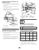
Form No. 3359-473 Rev B Foam Marker Kit for Multi-Pro® 1200, 1250, 5600, and 5700 Turf Sprayers and Workman® 200 Spray Systems Model No. 41236—Serial No. 00001 and Up Installation Instructions Note: Determine the left and right sides of the machine from the normal operating position. Safety Safety and Instructional Decals Safety decals and instructions are easily visible to the operator and are located near any area of potential danger. Replace any decal that is damaged or lost. 112-7890 1.
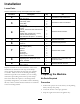
Installation Loose Parts Use the chart below to verify that all parts have been shipped. Procedure Description Qty.
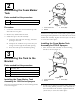
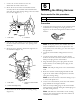
2 Assembling the Foam Marker Tank Parts needed for this procedure: 1 Foam marker tank 1 Tank cap, black Figure 1 Procedure 1. Foam marker tank 2. Washer 1. Locate the foam marker tank and black cap with filter tube in loose parts. 3. Screw (M6) Install 4 screws (M6) and 4 washers (M6) up through the mounting bracket platform to the underside of the foam marker tank assembly. Tighten all screws (45 to 61 lb-in) to secure the tank in place. 2. Remove any debris inside the tank. 3.
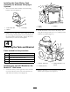
Installing the Foam Marker Tank Assembly for Workman 200 Sprayer Systems 1. Place the foam tank assembly on the mounting bracket as shown (Figure 3). Figure 4 1. Knobs 2. Battery Figure 3 1. Foam marker tank 2. Washer 3. Retainer 3. Screw (M6) 2. Install the bracket to the holes in the battery box using the 4 carriage bolts (3/8 x 1-1/4 inches) and 4 locknuts (3/8 inch) (Figure 5). 2.
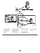
Installing the Tank and Bracket on the Multi-Pro® 5700-D 1. Position the sprayer on a level surface, set the parking brake, stop the pump, stop the engine, and remove the ignition key. 2. At the right rear fender, loosen the 4 bolts at the front and rear of the fender. 3. Install the bracket to the holes in the right rear fender using 4 carriage bolts (5/16 x 1 inch) and 4 locknuts (5/16 inch) as shown in Figure 6. Figure 7 1. Bracket, Workman 200 4. Handle 2. Bolt (3/8 x 1 inch), existing 5.
Routing the Foam Hoses to the Booms 1. Install the foam hoses to the booms. Note: Install the shorter length of hose to the boom on the same side as the bracket; install the longer hose to the boom on the opposing side to the bracket. A. On the right boom, install the foam hose along the rear side of the upper support pole (Figure 8). Important: The foam hoses will be pinched when the booms are in the “X” transport position if they are installed on the wrong side. Figure 9 1. Plastic tie C.
1. Locate the 16-foot foam hose for the dashboard-mounted control valve. 6 2. Route the hose from the foam marker bracket forward, below the chemical tank and behind the fuel tank, along with existing wiring to the area under the seat box (Figure 11). Installing the Wiring Harness Parts needed for this procedure: 1 Wiring harness, foam marker 4 Plastic tie Procedure 1.
. Ensure that the final plug is in position near the mounting bracket so that the foam marker assembly can be connected once it is installed. 9. Tie back any loose wiring along the harness to avoid snagging during operation. Figure 14 1200 series 1. Foam marker connector from vehicle main wiring harness (if existing) 2. Foam marker tank assembly 5. Foam marker connection 7. Left and right solenoid foam marker wiring harness plugs on the main wiring harness 3.
Figure 15 5700-D 1. Foam marker connector from vehicle main wiring harness (if existing) 2. Foam marker tank assembly 5. Foam marker connection 7. Left and right solenoid foam marker wiring harness plugs on the main wiring harness 3. Black power plug (on older vehicles) main wiring harness, tagged foam marker 4. Power plug from foam marker wiring harness 6.
Figure 16 Workman 200 series 1. Foam marker connector from vehicle main wiring harness (if existing) 2. Foam marker tank assembly 5. Foam marker connection 7. Left and right solenoid foam marker wiring harness plugs on the main wiring harness 3. Black power plug (on older vehicles) main wiring harness, tagged foam marker 4. Power plug from foam marker wiring harness 6.
7 Installing the Foam Nozzles Parts needed for this procedure: 2 Hose clamps (blue) 2 Hose clamps (white) 4 Brackets 4 Spacers 4 Set screws 2 Mounting rod 2 Foam nozzle assemblies Procedure 1. Install a plastic tube clamp to the exposed foam tubes. Use a blue clamp for the blue (fluid) tube and a white clamp for the clear (air) tube (Figure 17). Figure 17 1. Blue tube 2. Blue tube clamp 3. Clear tube 4. White tube clamp 2. Locate the foam nozzle mounting brackets and spacer.
Figure 18 1. Upper boom support pole 2. Bracket clamp half, lower 3. Spacer, note orientation 4. Bracket clamp half, upper 5. Screw, clamp 6. Nut, spacer 3. Install the second bracket assembly 3 to 4 inches inboard from the first bracket. 4. Install a set screw in the top hole of each spacer. 5. Install the mounting rod, with the splined end outward, into the holes in the spacers. Use the set screws to secure the rod in the desired position. 6. Locate the foam nozzles in loose parts.
8 Installing the Foam Control Valve and Connecting the Hoses Parts needed for this procedure: 1 Regulating valve, cap mount 1 Regulating valve, dashboard mount 1 Decal, 112-7890 Installing the Foam Control Valve on Multi-Pro 1200 Series Turf Sprayers and Workman 200 Spray Systems 1. Locate the black cap on the end of the foam marker tank assembly. 2. Install the 3-foot loop-back hose and cap mount regulating valve to the black cap (Figure 20). Figure 19 1. Mandrel, splined end 2. Foam nozzle 3.
B. Remove the white tube clamp from the hose barb on the tank cap not connected to the blue filter tube inside the tank. C. Install the white clamp over the clear tube, install the clear tube onto the hose barb, and secure the clear tube with the white clamp. D. Locate the cap mount regulating valve in loose parts. Note: This valve is black with one washer. E. Remove the blue tube clamp from the hose barb on the tank cap connected to the blue filter tube inside the tank. Figure 21 F.
Figure 22 Installing the Foam Control Valve on Multi-Pro 5700-D Turf Sprayers 1. Locate the foam hose previously routed forward to the cab. 2. Install a plastic tube clamp to the exposed foam tubes. Note: Use a blue clamp for the blue (fluid) tube and a white clamp for the clear (air) tube. 3. Make a mark inward from the right side of the dashboard 10 inches and then 1-1/2 inches from the bottom of the dashboard (Figure 23). Figure 23 1. Drill hole, 7/16 inch diameter 2. 10 inches 3. 1-1/2 inches 4.
5. Locate the dashboard mount regulating valve that can be disassembled in loose parts. 6. Loosen the nut that secures the knob assembly to the tee fitting as shown in Figure 24. Figure 24 1. Dashboard 2. Knob, dashboard mount regulating valve 3. Body, dashboard mount regulating valve 4. Ferule, blue tube 5. Ferule, clear tube 6. Blue tube Figure 25 7. Clear tube 1. Decal 112-7890 Connecting the Hoses on Multi-Pro 5700-D Turf Sprayers 7.
Figure 26 1. Clear tube and blue clamp (return tube from dashboard mount control valve) 2. Clear tube and white clamp (single use clear tube of 3-foot loop-back hose) 3. Right boom, clear tube and white clamp 4. Right boom, blue tube and blue clamp 5. Left boom, blue tube and blue clamp 6. Left boom, clear tube and white clamp B. Locate the short, loop-back hose previously cut, and install the clear tube to the remaining barb on the black, tank cap shown in Figure 26.
Figure 27 18
9 Installing the Switches and Fuse Parts needed for this procedure: 2 Rocker switch 1 Fuse, 15-amp Figure 29 1250 Multi Pro 1200 or 1250 Turf Sprayer 1. Plug 2. Switch 1. Remove the spray control panel to expose the bottom side. 2. Lift and remove the 2 plugs from the spray control panel on the vehicle, and install the 2 rocker switches provided in their place (Refer to Figure 28 for the Multi Pro 1200 and Figure 29 for the Multi Pro 1250). 3. Notch (at back) 4. Spray control panel 3.
Note: Ensure that the notch/hole on the bottom of each switch is oriented toward the rear of the vehicle. 5. Plug the connector labeled for the right foam solenoid to the right switch and the connector labeled for the left foam solenoid to the left switch. 6. Install the switch panel and secure the latch. 7. Screw the throttle knob onto the throttle rod until it is hand tight. Figure 32 8. Insert the 15-amp fuse in the corresponding slot in the fuse block located at the front of the vehicle. 1. 15-amp 2.
Operation Using the Controls Right boom switch—activates the compressor, generating a flow of water and air to the right boom section. Left boom switch—activates the compressor, generating a flow of water and air to the left boom section. Note: You can drop the foam simultaneously from both boom sections. Figure 33 1. 1/4 turn open Indicator markings—located on the side of the tank, they indicate the solution level in the tank. 6. Start operating the marking system and make a test pattern on the ground.
Maintenance Storage Winterizing 1. Position the vehicle on a level surface, set the parking brake, stop the pump, stop the engine, and remove the ignition key. 1. Relieve the pressure within the tank by pulling the release valve on the tank. 2. Relieve pressure within tank by opening the tank fill cap, install the tank fill cap, and hand tighten it. 2. Disconnect the air and liquid tubing from the tank cap. 3. Disconnect the air and liquid tubing from the tank. 3.
Notes: 23