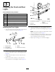
Form No. 3405-939 Rev A Road Light and Homologation Kit Multi Pro® 1750 Turf Sprayer Model No. 41250—Serial No. 314000001 and Up Installation Instructions This kit is designed to add the light components required for on-road travel. It is a dedicated attachment for a turf spray application vehicle and is intended to be used by professional, hired operators in commercial applications. Customer Service and have the model and serial numbers of your product ready.
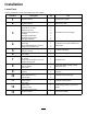
Installation Loose Parts Use the chart below to verify that all parts have been shipped. Procedure 1 2 Description Use Qty. No parts required – Prepare the machine. No parts required – Remove the seat.
Procedure Description Use Qty. 14 Lock-mount bracket Latch Grip Hex-head screw (12 x 30 mm) Locknut (12 mm) 1 1 1 1 1 Install the seat lock. 15 No parts required – Install the seat.
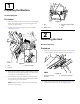
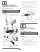
1 Preparing the Machine No Parts Required Procedure 1. Move the machine onto a level surface, set the parking brake, shut off the pump, shut off the engine, and remove the ignition key. Figure 3 2. Unlatch the seat by pushing the seat-latch handle rearward (Figure 2). 1. Nut 3. Terminal (positive-battery cable) 2. Battery post 4. Bolt 2 Removing the Seat No Parts Required Procedure 1. Remove the electrical connector of the chassis harness that connects to the seat-switch connector (Figure 4).
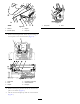
Figure 7 1. Seat plate Figure 5 1. Washer 3. Hairpin 2. Bracket (seat) 4. Prop rod 3. Remove the 2 hairpins that secure the pivot fitting of the seat plate to the chassis brackets (Figure 6). Figure 6 1. Seat plate 4. Pivot fitting (seat pan) 2. Seat 3. Hairpin 5. Chassis bracket 6. Pivot pin 4. Remove the 2 pivot pins that secure the seat and seat plate to the chassis (Figure 6). 5. Lift the seat and seat plate up and out of the machine (Figure 7). 5 2.
3 Installing the Front and Rear Lights Parts needed for this procedure: 1 Headlight support 3 Bolt (5/16 x 2-1/4 inch) 3 Washer (5/16 inch) 3 Flanged locknut (5/16 inch) 2 Headlight 1 Rear-light bracket (left) 1 Rear-light bracket (right) 2 Rear-light assembly Figure 9 1. Threaded post (headlight) 4. Vertical hole (front-light support) 2. Joint half 5. Locknut (10 mm) 3. Serrated shell Installing the Front Lights 5.
Installing the Rear Lights 6. Repeat steps 4 and 5 at the other rear-light bracket at the other end of the center-boom channel. 1. Align the holes of the rear-light bracket with the 2 holes in the center-boom channel. 4 Note: The left and right rear-light bracket are unique. Ensure that the short flange of the bracket is flush with the surface of the channel. Installing the Speed Signs and License Plate Brackets Parts needed for this procedure: 3. Locknut (5/16 inch) 2.
3. Remove the backing from a speed decal. 4. Align the top and forward edges of the sprayer decal (B of Figure 12) with the tape marks that you made in steps 2 and 1. 5. Press the decal onto the surface of the tank from the top down while removing air bubbles as you apply the decal. 6. Remove the masking tape from the tank. 7. Repeat steps 3 though 6 at the other side of the tank. Installing the Speed Sign the Center-Boom Section 1. Remove the backing from a speed decal (A of Figure 13). Figure 14 1.
Installing the License Plate Brackets 1. Assemble the license-plate bracket to the support bracket with the 2 flange-head bolts (5/16 x 3/4 inch) and 2 flange locknuts (5/16 inch) as shown in Figure 15. Figure 15 1. Flange-head bolts (5/16 x 3/4 inch) 3. Support bracket 2. License-plate bracket 4. Flange locknuts (5/16 inch) 2. Align the holes in the support bracket with the holes in the frame of the center-boom section (A of Figure 16). Figure 16 1. Flange-head bolts (5/16 x 3/4 inch) 3.
2. Align the data plate to the platform channel as shown in Figure 17 and mark the 4 hole locations. 5 3. Centerpunch the platform channel at the 4 marks (Figure 17). Installing the Data Plate 4. Drill 4 holes 3 mm (1/8 inch) through the channel at the centerpunch marks (Figure 17). For Machines Operated In Germany 5. Rivet the data plate to the platform channel (Figure 18). Parts needed for this procedure: 1 Data plate 4 Rivet (5 x 10 mm) Procedure 1.
2. Rotate the 90° bracket as shown in Figure 20 and loosely secure it to the mounting stud of the horn assembly with the nut that you removed in step 1. Note: You will tighten the nut of the horn assemble in a later procedure. 3. Align the hole in the short leg of the 90° bracket with the hole in the rear-platform channel (Figure 21). 4. Assemble the 90° bracket to the platform channel with the flange-head screw (5/16 x 3/4 inch) and the flange locknut (5/16) as shown in Figure 21. Figure 19 1.
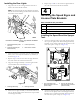
Installing the Main-Block Fuse 8 Insert the fuse into the main-block frame (Figure 23). Installing the Flasher Module and the Main-Block Fuse Parts needed for this procedure: 1 Flasher module 1 Push-in fastener 1 Fuse (15 A) Figure 23 Installing the Flasher Module 1. Fuse (15 A) 1. Align the flasher module with the hole in the frame of the machine (Figure 22). 2. Insert the push-in fastener through the hole in the flasher module and the frame of the machine (Figure 22). Figure 22 1.
9 Routing and Installing the Wire Harness to the Machine Parts needed for this procedure: 1 Wire harness 6 Cable tie Preparing to Route the Wire Harness Use the following graphic for an outline of routing the wire harness to the machine (Figure 24).
Routing the Wire Harness to the Side Console 1. Route the harness through the front of the seat shroud (Figure 25). Figure 27 1. Ring terminal 2. Positive (+) battery post Routing the Wire Harness to the Turn-Signal Figure 25 1. Opening in the front of the seat shroud 1. Remove the 2 bolts that secure the hose cover to the machine and remove the hose cover (Figure 28). 2. Route the harness to the side console (Figure 26). Figure 26 Figure 28 1. Harness 1.
Figure 31 1. Horn 3. Terminal of the wire-harness leg 2. Terminal of the horn 3. Tighten by hand the nut that secures the horn to the 90° bracket; refer to Figure 20 in 7 Installing the Horn (page 11). Figure 29 1. Turn-signal switch 2. 8-socket connector Routing the Wire Harness to the Headlights Routing the Wire Harness to the Horn 1. Route the wire harness through the grommet at the hole in the rear-angle platform to the horn (Figure 30). 1.
Routing the Wire Harness to the Taillights 1. Route the tail light leg of the wire harness from the flasher module rearward along the right-frame tube between the frame tube and the engine (Figure 35). Figure 33 1. 6-socket connector 3. Right headlight 2. 6-pin connector 5. Repeat step 4 for the left headlight. 6. Assemble the hose cover to the floor of the operator’s platform with the 2 bolts that you removed in removed in step 1 of Routing the Wire Harness to the Turn-Signal (page 14). Figure 35 1.
Figure 39 1. Tail light 3. 4-pin connector 2. 4-socket connector 7. Repeat step 6 for the other tail light. Figure 37 1. Wire harness 10 3. 4-socket connector (LEFT REAR TURN/BRAKE SIGNAL) 2. Boom-valve bracket Installing the License-Plate Light 4. Route the wire harness to the left of the flow meter and toward the boom-frame channel (Figure 38). Parts needed for this procedure: 1 License-plate light 1 Screw (#10 x 5/8 inch) 2 Locknut (#10) Procedure Figure 38 1.
2. Align the lens for the light down and the holes in the light with the holes in the license-plate bracket (Figure 41). Figure 42 1. Hole plug 2. Side-console mount 2. Route the 8-socket connector of the wire harness through the hole in the side-console mount (Figure 43). Figure 41 1. License-plate light 3. Screw (#10 x 5/8 inch) 2. Locknut (#10) 4. License-plate bracket 3. Assemble the light to the bracket (Figure 41) with the 2 screws (#10 x 5/8 inch) and 2 locknuts (#10).
12 Installing the Light Switch and the Horn Button Parts needed for this procedure: 1 Horn switch 1 Button cover 1 3-position switch 1 Light-switch decal (plain) Figure 46 1. Control-panel cover 2. Choke control 4. Remove the round plug from the control-panel cover (A of Figure 47). Installing the Horn Switch 1. Remove the knob from the differential-lock rod (Figure 45). 2. Remove the 4 hex-head screws (1/4 x 1/2 inch) as shown in Figure 45. Figure 45 1. Knob 2.
Figure 48 1. Horn switch 2. 2-pin connector Installing the Light Switch Figure 50 1. Remove the existing 8-socket connector from the old light switch (Figure 49). 1. Socket connector 2. Light-switch connector (slot number 1) 4. Install the light-switch decal onto the control-panel cover, centered over the light switch opening, with the words SONIC BOOM toward the back of the machine (Figure 51). Figure 49 1. Control-panel cover 3. 8-socket connector 2. Old light switch Figure 51 2.
13 Connecting the Battery No Parts Required Procedure Figure 52 1. 3-position switch 1. Align the ring terminal for the machine wire harness, ring terminal of the kit wire harness, terminal for the positive battery cable to the positive battery post (Figure 54). 2. 8-socket connector (with the line in slot number 1) 7. Align the control-panel cover to the side console (Figure 53). Figure 53 1. Control-panel cover 2. Side console Figure 54 8.
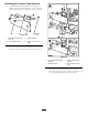
4. Align the lock bracket and the clevis pin through the hole of the outboard-seat gusset (Figure 56). 14 5. Align the holes in the latch with the holes in the seat gussets (Figure 57). Installing the Seat Lock Parts needed for this procedure: 1 Lock-mount bracket 1 Latch 1 Grip 1 Hex-head screw (12 x 30 mm) 1 Locknut (12 mm) Figure 57 Procedure 1. Seat gussets 1. Remove the hairpin from the clevis pin (Figure 55). 2. Latch 6.
8. Fully insert the clevis pin through the holes in the seat latch and the inboard-seat gusset. 9. Secure the lock bracket to the outboard-seat gusset with the hex-head screw (12 x 20 mm) and the locknut (12 mm) as shown in Figure 60. Figure 62 1. Seat and seat pan 3. Insert the 2 pivot pins that secure the seat and seat pan to the chassis (Figure 63). Figure 60 1. Hex-head screw (12 x 30 mm) 3. Outboard-seat gusset 2. Lock bracket 4.
Operation 7. With seat latched, ensure that the grip of the lock-mount bracket is facing down. Using the Headlights Move the light switch on the side console rearward toward the sloped end of the switch to turn the headlights to the ON position (Figure 65). Figure 65 1. HEADLIGHTS ON position (sloped end of the switch) 3. WORKLIGHTS ON position (rounded end of the switch) 2.
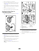
Maintenance Using the Horn Push down on the horn button to sound the horn (Figure 67). Replacing Light Bulbs Replacing a Headlight Bulb 1. Ensure that the light switch is in the OFF position. 2. Remove the 6 screws securing the headlight (Figure 69). 3. Remove the headlight cover (Figure 69). Figure 67 1. Horn button Using the Turn Signals Move the turn-signal switch up to indicate a right-turn signal (Figure 68). Move the turn-signal switch down to indicate a left-turn signal (Figure 68). Figure 69 1.
Replacing a Tail-light Bulb Replacing a License Plate Bulb 1. Ensure that the light switch is in the OFF position. 1. Remove the 2 screws that secure the cover to the base of the license-plate light, and remove the cover (A of Figure 71). 2. Remove the 2 screws that secure the cover and lens to the tail-light base. 3. Remove the tail-light cover. 4. Pushing down on the pin on the light bulb, rotate the light bulb to the left, and pull the light bulb out (Figure 70). Figure 70 1. Pin 2. Light bulb 5.
Replacing Fuses Replacing Fuse Block Fuse The electrical system is protected by fuses, and requires no maintenance. If a fuse blows, check the component or circuit for a malfunction or short. 1. Pull out the open fuse. 2. Replace the open fuse with a new fuse (Figure 72). Note: Ensure that the correct-size fuse is installed. Figure 72 1. Fuse 2. Fuse slot Replacing the Tail-light Fuse Figure 73 Note: Your machine has separate fuses for the left and right taillights. 1. Cover 2. Fuse 3.
Notes:
Notes:
Notes:
International Distributor List Distributor: Agrolanc Kft Asian American Industrial (AAI) B-Ray Corporation Brisa Goods LLC Casco Sales Company Ceres S.A. CSSC Turf Equipment (pvt) Ltd. Cyril Johnston & Co. Cyril Johnston & Co. Fat Dragon Femco S.A. FIVEMANS New-Tech Co., Ltd ForGarder OU G.Y.K. Company Ltd. Geomechaniki of Athens Golf international Turizm Hako Ground and Garden Hako Ground and Garden Hayter Limited (U.K.) Hydroturf Int. Co Dubai Hydroturf Egypt LLC Irrimac Irrigation Products Int'l Pvt Ltd.
The Toro Warranty A Two-Year Limited Warranty Conditions and Products Covered The Toro Company and its affiliate, Toro Warranty Company, pursuant to an agreement between them, jointly warrant your Toro Commercial product (“Product”) to be free from defects in materials or workmanship for two years or 1500 operational hours*, whichever occurs first. This warranty is applicable to all products with the exception of Aerators (refer to separate warranty statements for these products).