
Installation Instructions

2
8. Lift and secure the Mounting Frame and
Spreader approximately 12 inches above ground
level for easier access to fasteners used in secur-
ing the Spreader to the Mounting Frame.
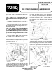
9. Install hex nut and washer to 5/8" x 2" bolt at
rear mounting plate. See FIG. 2.
10. Insert two U-bolts over the tubular frame
of the Spreader and secure with four 3/8" flat
washers and lock nuts (FIG. 2).
11. Secure the cross member of the Spreader
to the Mounting Frame with two 3/8" x 1" bolts,
four washers, and lock nut. See FIG. 3.
12. Tighten all fasteners securely. Apply thread
locking adhesive and tighten the set screw in the
End Yoke. Re-install the Drive Shaft Cover.
13. Install the Edge Trim on the Radiator Cover.
Mount the Radiator Cover on the Vehicle Frame
and secure with four 3/8" x 1" bolts and flat wash-
ers. On some models, it may be necessary to use
two nuts at rear holes.
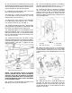
14. Locate and remove two 1/2" bolts on each
side of the Workman frame and install the Attach-
ment Mounting Brackets, using the bolts and nuts
removed earlier. See FIG 4. Tighten the nuts
and bolts securely.
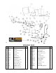
1. Attachment Mounting Bracket
NOTE: If the Workman vehicle is equipped
with the optional PTO Kit, remove the bottom
fasteners, loosen the top fasteners and tilt the
PTO Shield downward. This is necessary BE-
FORE the Mounting Frame can be assembled
to the Workman Frame.
15. Position the assembled Spreader and
Mounting Frame onto the Workman.
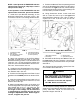
17. Remove the Knobs to release the hinged
door on the Belt Cover and install the Spreader
Spring as shown in FIG. 5. Install the Drive Belt
between the Gear Reducer Pulley and the
Workmans Electric Clutch Pulley. Close the cover
and re-install Knobs.
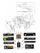
1. Drive Belt 3. Idler Pulley
2. Gear Reducer Pulley 4. Idler Spring
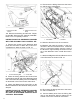
18. Mount the Rear Support to the Mounting
Frame and secure with two 1/2" x 3-1/4" bolts,
four flat washers, and two lock nuts on each side
of the Mounting Frame. Do not tighten bolts. See
FIG. 6.
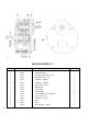
1. Rear Support 3. Support Tube Plates
2. Mounting Pin 4. Lynch Pin
19. Slide the two 3/4" x 4-3/8" Mounting Pins
through the Support Tube Plates and the
Workmans frame. Secure with two Lynch Pins
on each Mounting Pin. Torque fasteners for Rear
Support to 75 ft. lbs.
FIG. 4
FIG. 5
FIG. 6
16. Secure the Mounting Frame to the Attach-
ment Mounting Brackets with two 1/2" x 1-1/2"
bolts four washers and lock nuts. See FIG. 4.
1400
1401
1402