
Installation Instructions

3
If the Spreader is NOT EQUIPPED with the
optional Flow Control Kit, proceed as follows:
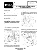
1. Install the Lever Bracket Assembly on the
Workmans Seat Frame as shown in FIG. 7. Se-
cure with four 5/16" x 3/4" carriage bolts and nuts.
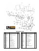
1. Lever Bracket Assy 4. Lever Bracket Brace
2. Seat Frame 5. Flow Control Handle
3 Flow Regulator Handle (in Close position)
(in Close Position)
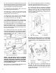
2. Apply rust preventive oil to the Pivot Sleeve
and slide it inside the pivot tube on the Lever
Bracket Assembly, position a 1/2" flat washer and
insert the 1/2" x 4" bolt through the washer, the
pivot tube, the Lever Bracket Brace and the Con-
trol Lever. Secure with a lock nut.
3. Install the Lever Bracket Brace to the hole in
the Spreaders frame, using a 5/8" x 1-1/2" screw,
two washers and a lock nut.
4. Position the Flow Regulator and Flow Control
Handles in their CLOSE position as shown in FIG.
7.
5. Insert the Linkage Rod into the lower hole of
the Control Lever and secure with two 1/2" flat
washers and cotter pin.
6. Attach the adjustable clevis on the other end
of the Linkage Rod to the Spreaders Flow Regu-
lator Handle with a 1/2" x 1-1/2" clevis pin, two
washers and hairpin cotter. NOTE: The effec-
tive length of the Linkage can be shortened
or lengthened by loosening the jam nut and
turning the Adjustable Clevis. When length is
correct, re-tighten the jam nut.
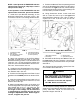
Shown With R.H. Seat Back Removed
7. Position the Muaual Tube the passenger hand
side of the Seat Back Rest Channel, it will have to
be moved to the right hand side, with R-Clamps
posiotioned as shown in FIG. 8. If the existing hole
in that locatoin proceed as follows:
8. Using dimensions shown, locate, mark and
drill an 11/32" dia. hole in top of the right hand
Seat Back Rest Channel. Use a file to make a
square hole of the 11/32" dia. hole (for the car-
riage bolt head.)
NOTE: If the Spreader IS EQUIPPED with the
optional Flow Control Kit, skip Steps 1 thru 6
and proceed to Step 7.
FIG. 7
FIG. 8
1403
1404
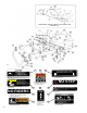
1. Back Rest Channel 3. Manual Tube
2. R-Clamps 4. Open/Close Decal
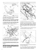
9. Re-install the R-Clamps and Manual Tube on
the right hand side of the channel, using the fas-
teners previously removed and hex nut provided.
See FIG. 8.
10. Remove backing and affix Open/Close De-
cal on Seat Frame. See FIG. 8.
DANGER
AN OVERLOADED SPREADER HOP-
PER CAN CAUSE A TIP OVER RESULT-
ING IN SERIOUS INJURY OR DEATH.
l Install the Level Limit and Capacity
700 LBS. Decals as instructed.
11. Remove the backing and affix the Maximum
Sand Level Decal directly below the existing Ca-
pacity 1000 LBS. Decal, on the back of the
Spreader Hopper. See FIG. 9.