
Installation Instructions

4
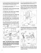
top of the Workman frame. Install Grommet in
hole.
7. Attach the Magnet and Control Box to the front
of the Enclosure as shown in FIG. 10.
1408
FIG. 12
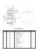
1. Control Box
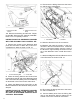
8. Re-connect the Wiring Harness to the Actua-
tor and Limit Switches.
9. Connect battery wires from the Wiring Har-
ness to the Workman Vehicles battery as de-
scribed in the Flow Control Kit instructions.
1. Limit Switch 2. Actuator
5. Slide the Grommet over the connectors.
6. Measure and mark the location, to drill a 2"
dia. hole in the rear of the Enclosure. Locate the
hole in a convenient location near the center of
the Enclosure, approximately 24 inches from the
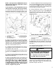
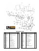
1. Capacity 700 LBS. 2. Maximum Sand Level
Decal Decal
12. Remove the backing and affix the Capac-
ity 700 LBS. Decal over the Capacity 1000 LBS.
Decal, so it is completely covered.
INSTRUCTIONS FOR SPREADER EQUIPPED
WITH THE OPTIONAL FLOW CONTROL KIT:
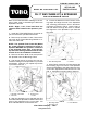
1. Remove two screws on the Workman dash
panel and use them to attach the Control Con-
sole Bracket to dash as shown in FIG. 10.
1. Console Mounting Brkt 2. Control Box
2. Route the Wiring Harness and Control Box
forward along the left side of the Workman frame
and connect the two battery wires to the Battery,
as described in the Flow Control Instructions.
3. Attach the Magnet and Control Box to the
Bracket attached to the Workman dash panel in
Step 22.
INSTRUCTIONS FOR SPREADER EQUIPPED
WITH THE OPTIONAL FLOW CONTROL, TO
BE USED ON WORKMAN EQUIPPED WITH
OPTIONAL ENCLOSURE.
4. Disconnect the Wiring Harness at the Actua-
tor and the two Limit Switches.
FIG. 9
FIG. 10
FIG. 11
1405
1407
1406