
Installation Instructions


G010813
1
2
3
4
Figure2
1.Bedmountingplate
3.Clevispin
2.Cylinderrodend
4.Lynchpin
12.Removetheclevispinand2lynchpinssecuringeach
setofpivotplatestotheframechannels(Figure3).
G010814
1
2
3
4
Figure3
1.Vehicleframechannel3.Clevispin
2.Pivotplate4.Lynchpin
13.Carefullyremovethebedfromthevehicleframe.
14.Removethe2angeheadboltsandangelocknuts
securingtherearofeachengineframemounting
brackettoeachsideofthevehicleframe(Figure4).
G010815
1
2
3
Figure4
1.Engineframemounting
bracket
3.Attachmentmounting
bracket
2.Vehicleframe
15.Looselysecureanattachmentbrackettoeachengine
framemountingbracketandthevehicleframe
withthe2angeheadboltsandangelocknuts
previouslyremoved(Figure4).
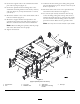
16.Mountthespreaderdrivetothesupportchannel
with2bolts(M12x65mm),2bolts(M12x40mm),
and4nuts(M12)(Figure5),providedwiththe
spreader.
G010816
1
2
3
4
5
6
Figure5
1.Spreaderframe
4.Frontsupporttube
2.Spreaderdrive5.Rearsupporttube(2)
3.Supportchannel6.Upperframe
17.Looselymountthefrontsupporttubetothe
spreaderframewith2bolts,4washers,and2nuts
(Figure5).
18.Looselymounteachrearsupporttubetothe
spreaderframewith3angeboltsand1angenut
(Figure5).
19.Looselymounttheupperframetothesupporttubes
with4angeboltsandangenuts(Figure5).
20.Positionthespreaderframeontothevehicleframe
aligningthemountingtabswiththeattachment
brackets(Figure6).
21.Looselymountthesupporttubetorearofthe
spreaderbasewith4bolts,8washers,and4nuts
(Figure6).
3