FORM NO. 92-3514 OPERATOR'S, SET-UP, MODEL NO. 41403-40001 & UP AND PARTS MANUAL L SPREADER FLOW CONTROL. J To assure maximum safety, optimum The safety alert symbol means CAUTION, performance, and to gain knowledge of the WARNING, or DANGER — personal product, it s essential that you or any other safety Instruction. Failure to comply with the operator of this requirement read and instruction may result in personal injury. understand the contents of this manual before the vehicle engine is ever started.
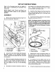
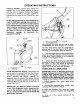
SET-UP INSTRUCTIONS Refer to the illustrated parts flits for details of parts used in assembling the Spreader Flow Control Kit. NOTE: "Right", "Left", "Front" and "Rear" are referenced while seated in the operator's position, ASSEMBLY: 1. Remove the Actuator Mounting Angle from the Flow Control Kit. See FIG. 1. Actuator Assembly FIG. 5. Actuator Mounting Front Limit Switch Angle Rear Limit Switch 8. Spreader Mounting BRD Actuator Straps Casting 2.
wigs and connect the red wire to the Battery's positive post and the black wire to the negative post. NOTE: The toggle switch on the Control Box is used to control the Actuator action. When the toggle switch is positioned at "OPEN", as designated by the decal, the Actuator is extended and the regulator disc in the Hopper should open. When the toggle switch is positioned at "CLOSE", the Actuator is retracted and the regulator disc should close. When the toggle switch.is.in.the center.
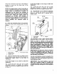
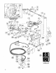
ADJUSTING THE REAR LIMIT SWITCH: 1. Moving the toggle switch toward "OPEN", slowly extend the Actuator until the front edge of the Flow Central Handle is at the “7* position on the Regulator's scale. See FIG. Fig. 5 1. Frost Limit Switch 2. Switch Guide 8. Actuator Pin Nuts 4. Rear Limit Switch 5. Switch Guide Jam 2. Loosen the jam nuts on the Switch Guide and slide it forward until the button on the rear Limit Switch is depressed approximately 1/8" by the Actuator Pin.
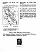
OPERATING INSTRUCTIONS TOGGLE SWITCH: Opens and closes the regulator disc in the Hopper opening, to start or stop the flow of malarial. Position the Toggle Switch at the "FEN" or "CLOSE" position as indicated by the decal on the Control Box. See FIG. 1. NOTE: After positioning the Limit Switches for a full "CLOSE" disc opening, as described on page 4, the Front Limit Switch should not need to be adjusted again.
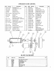
SPREADER FLOW CONTROL flee Part No. Description Qty Ret] Part No. Description 1 [24-16-AD Flat Washer, 41448 Knob 2 192--0302 Adjustable Clevis, 1/2 NF 2 21192-0304 Witch Guide 3 [92-0803 Pivot Spacer 2 22920024 Clevis Pin, 1/2 4 |a28067 Hair Pin Cotter 4 Spacer, 34 OD.
The Toto Promise A One Year Limited Warranty The Toto Company promises {0 repair your model 41403 Spreader Flow Control Kit if defective in materials or workmanship. The following time periods from the date of purchase apply special warranty terms, on certain components, may be offered through The Toto Company by the component manufactures: Commercial Products The cost of pasts, labor and transportation are included.