
Installation Instructions

1
SET-UP AND
PARTS LIST
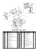
Refer to the illustrated Parts List for the details of
parts used in assembling the Hose Reel Kit.
NOTE: If this Hose Reel Kit is being used
on a Multi Pro 5500 model 41564 that is
equipped with an Enclosed Boom System
model 41355 then a Pin Receiver Adapter
Kit part NO. 95-2425 must be obtained
through an authorized TORO Dealer.
MOUNTING HOLES:
1. Disconnect negative battery terminal from
the Battery.
2. If assembling the Hose Reel onto a Multi Pro
5500 with a serial number below 41564-70001,
three (3) mounting holes must be drilled.
(See Step 3) For vehicle with serial number
41564-70001 and above proceed to the Frame
Assembly section of this manual.
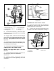
3. Drill one (1) 7/16" dia. hole in the tank saddle
and two (2) 7/16" dia. holes in the hydraulic tank
mount. See FIG 1.
HOSE REEL KIT
for the Multi-Pro
®
5500
FORM NO. 95-2189 REV. A
FIG. 1
1. Front of Tank Saddle 2. Hydraulic Tank Mount
1005
©The Toro Company - 2000
All Rights Reserved
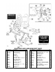
FRAME ASSEMBLY:
NOTE: Refer to the parts list illustration
on page 3 for additional assembly
assistance.
1. Install the Mounting Legs Assembly onto the
Hydraulic Reservoir Mount using two (2) 3/8" cap
screws, hex nuts and flat washers. (Refer to Fig.
2 on page 2) Tighten the fasteners to "just snug"
to permit any necessary adjustments.
2. Install the two (2) Mounting Arms to the
Spray Tank Saddle and the Mounting Legs
Assembly using four (4) 3/8" cap screws, hex nuts,
and flat washers. Tighten all six (6) 3/8" cap screws
at this time.
3. Install the Hose Reel Assembly onto the two
(2) Mounting Arms, using the four 3/8 x 1" cap
screws, flat washers and lock nuts. Attach the
Hose Clip under the right Mounting Arm before
tightening the Bolts. See FIG. 2.
4. Crimp the 3/8" ring terminal to the
NEGATIVE (-) wire from the Reel Motor. Ground
the NEGATIVE (-) wire to the left-rear screw used
to mount the Hose Reel Assembly to the frame.
5. Tighten all fasteners securely in order to
insure a solid, rigid installation.
6. Attach the Electrical Box assembly to the
left side of the Hose Reel with two (2) 5/16" x 3/4"
cap screws and lock nuts.
7. Remove the screws holding the Cover to
the Electric Box, to gain access to the electrical
components mounted to the inside of the Box
Cover.
8. Feed the POSITIVE (+) wire from the Reel
Motor through the wire bushing in bottom of the
Electric Box. Crimp the #10 ring terminal to the
POSITIVE (+) wire.
MODEL NO. 41565