
Installation Instructions
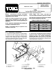

INSTALLATION
INSTRUCTIONS
CAB
for the MULTI-PRO
®
5500 Vehicle
FORM NO. 95-2410 REV. A
©The TORO Company - 2001
All Rights Reserved
Model No. 41567
Refer to the illustrated Parts List for the details of parts used in assembling this kit.
NOTE: Instructions include assembly
procedures for the ROPS Kit which is a required
supplement to the Cab Kit.
NOTE: For easier assembly, loosely assemble
parts during installation of the Cab, after
assembly, safely secure Cab by tightening all
hardware.
NOTE: SAVE ALL HARDWARE FOR LATER USE
UNLESS OTHERWISE NOTED.
NOTE: An assistant may be required in the
assembly of the Cab.
NOTE: "Right", "Left", "Front", and "Rear" are
referenced while seated in the Operator's Position.
Insert Anchors have been provided in the ROPS
Bar to allow installation of the Cab.
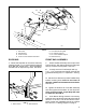
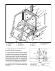
A/C Compressor Installation:
1. Disconnect negitive cable from vehicle battery.
2. Raise R.H. Seat, unplug Wire Harness Ass'y
and disconnect Vacuum Hose from ESC Module
located on R.H. Seat Box Panel. Loosen hose
clamp and separate 90° hose from Inlet Tube Ass'y,
that connects to Air Cleaner. See FIG 1.
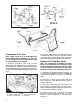
3. Remove R.H. Hip Restraint and R.H. Seat Box
Panel from vehicle. Air Filter assembly may remain
attached to panel. For added convenience,
remove R.H. Seat. Note: The R.H. Lower Rear
Mounting Bolt and Nut and the (3) bolts and
hardware from the front of the R.H. Seat Box Panel
may be discarded. See FIG 1.
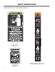
FIG. 1
1. ECS Module 4. R.H. Seat Box Panel 7. Air Intake Extension
2. Blower Wire Harness 5. R.H. Hip Restraint 8. 90 deg Hose
3. Air Cleaner 6. Air Inlet Cap 9. Inlet Tube Ass'y
1
2
3
4
5
6
7
8
9
1043
3/8" 25 FT. LB.
7/16" 45 FT. LB.
5/8" 150 FT. LB.
TORQUE SPECIFICATION CHART
BOLT SIZE TORQUE VALUE