
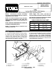
Installation Instructions

6
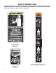
Side Panel Installation:
1. Mount Cab L.H. Side Panel assembly to L.H
Seat Box Panel. See FIG. 7.
a. Remove (2) side carriage bolts from L.H.
Hip Restraint.
b. Secure L.H. Side Panel to L.H. Seat Box
Panel with the (2) carriage bolts removed from
Hip restraint in Step a.
c. Secure L.H. Seat Box Panel, Front Seat
Box Panel, and Rubber Flap with 5/16" x 3/4"
capscrews, Spacers, and flange locknuts.
d. Secure L.H. Side Panel to Rear Cab
Panel with (2) 5/16" x 3/4" short shouldered
carriage bolts and flange locknuts.
2. Repeat Steps 'a. - d.' for R.H. Side of Vehicle.
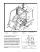
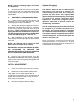
Blower & Cover Installation:
Note: Apply drop of oil to Refrigeration Line
O-Rings before installation. Use care not to
lose O-Rings after removing protective caps
from Refrigeration Line fittings.
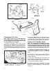
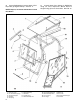
1. Set Enclosure Cover on top of the Rops Bar/
Front Bar Assembly. Hook the rear of the
Enclosure Cover over the back of the Rops Bar
and slide Cover forward. See FIG. 12.
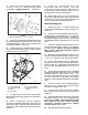
2. Remove protective cap and connect
Refrigeration Hose 95-2198 (large dia.) to top port
located on R.H. side of Blower Assembly (FIG 9).
3. Remove protective cap and connect
Refrigeration Hose 95-2199 (small dia.) to bottom
port located on R.H. side of Blower Assembly.
4. Loosely secure front of Blower Ass'y to
Enclosure Cover Assembly with (3) 1/4" flange
screws.
5. Swing Blower Assembly up and into place.
Loosely secure to Cross Tube Assembly with (3)
1/4" flange screws. See FIG. 9.
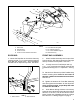
6. Slide Cross Tube forward as far as possible
and secure with (4) 3/8" x 1" capscrews.
7. Tighten Blower Mounting Securely.
Condenser Installation:
1. Place Condenser Mount Angles on top of the
Enclosure Cover Assembly. Loosely secure
Angles to the Cross Tube Assembly and Rops Bar
with (4) 3/8" x 1" capscrews (2 per angle). See
FIG. 12.
2. Secure Condenser to Condenser Mount
Angles using (4) 3/8" x 1" capscrews and flange
locknuts. See FIG. 12.
3. Tighten all fasteners securely.
4. Wrap hose insulation provided with kit
around large dia. hose (95-2198) extending from
blower housing. Route large dia. hose from Blower
Ass'y through 1" dia. hole in rear of Enclosure
Cover. Tighten jam nut on refrigeration line after
inserting through rear of Enclosure Cover.
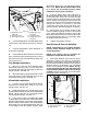
5. Route Refrigeration Hose 95-2199 from
Blower Assembly through 1-1/4" dia. hole in rear
of Enclosure Cover and connect to Condenser
Ass'y as illustrated in FIG 10.
FIG. 9
1. Cross Tube Ass'y 5. Enclosure Cover
2. Blower 6. Refrigeration Hose
3. Refrigeration Hose 95-2199
95-2198 7. Condensate Line
4. Blower Wire Harness