
Operator's Manual


3
The contents of the Foam Marker Tank are
under pressure. Loosening fittings under
this condition could result in personal
injury.
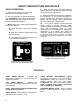
To relieve pressure from tank, flip the
Pressure Relief Valve UP (as shown on
page 2, decal # 94-7275)
OPERATION
FILLING AND ADJUSTING:
1. Ensure the Right and Left Boom Switches
located on the console are in the OFF position.
CAUTION
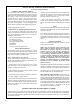
2. Flip the Pressure Relief Valve to the upright
position. (Fig. 1)
3. Pull up on the "Lid Clamp", turn the Lid 90°,
and remove from the tank.
4. Pour water through opening in top of tank.
Add proper amount of foam concentrate as
recommended by the manufacturer. DO NOT
EXEED 2-1/2 GAL. (9.46 LITERS) OF SOLUTION
IN TANK!
NOTE: Extreme PH levels (hardness/softness)
of water will affect the amount of foam
concentrate needed.
5. Reinstall the Lid of the Solution Tank. Make
sure the Lid is positioned properly for a tight seal,
and push down the Lid Clamp.
6. Close the Pressure Relief Valve.
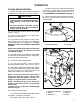
7. For first time operation, open the Foam
Density Adjustment Valve 1/8 to 1/4 turn. (Fig. 2)
8. Start marking system and make a test pattern
on the ground. When first starting the marker
system it can take 1 to 2 minutes to fill the line
before foam will flow from the boom(s).
NOTE: Foam left in the line for more than 2
hours may become watery. Before next
application, allow the system to run for 1 to 2
minutes to clear the lines of excess water.
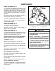
NOTE: The Mixer Tee (Fig. 3) can flood if the
solution to air mixture is too rich, producing
watery foam.
If foam is too dry, it will flow in unsteady high
pressure surges.
If a flooding condition exists:
A. Close the Foam Density Adjustment Valve
completely. Operate for 2 minutes.
B. Slowly reopen valve 1/8 to 1/4 turn.
C. Wait 1minute, then check the consistency
of the foam. Adjustments may be required to
achieve desired foam marker consistency. Refer
to FOAM DENSITY ADJUSTMENT VALVE pg. 2
9. When foam drops are at desired consistency,
spray by aligning Boom extentions to foam
marked trail(s).
Figure 1
1. Pressure Relief Valve 2. Lid Clamp
Figure 2
1. Foam Density Adj. Valve 4. Compressor
2. Strainer 5. Couplers
3. Check Valve 6. Air Filter