
Installation Instructions

1
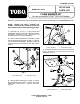
FOAM MARKER KIT
for use on the MULTI PRO
®
5500 Turf Sprayer
SET-UP AND
PARTS LIST
MODEL NO. 41574
FORM NO. 94-7246
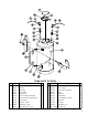
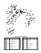
Refer to the illustrated Parts List for the details of parts used in assembling the FOAM MARKER 5500 KIT.
©The TORO Company - 1996
All Rights Reserved
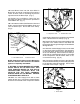
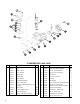
Fig. 2
1. Mixer Tee Ass'y 2. Center Boom Angle
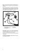
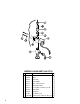
4. Release the latch and remove the Switch
Panel Assembly from the Center Console
Assembly. (Fig. 3)
NOTE: "RIGHT" and "LEFT", "FRONT" and
"REAR" reference the operator's directions
when seated in the normal operating position.
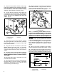
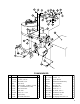
1. Remove four (4) 1/4" x 1" cap screws and
flatwashers holding Cover to the Tank/Compressor
Assembly. Remove Cover. Set cover and
fasteners aside for future reinstallation.
2. Mount Tank/Compressor Assembly to right
vehicle step frame using two (2) 3/8" x 1" hex hd.
cap screw and flatwashers. Fasteners must be
installed from the backside of the step frame.
(Fig. 1)
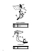
Fig. 3
1. Switch Panel Ass'y 2. Panel Release Latch
Fig. 1
1. Right Step Frame 2. Tank Ass'y Frame
3. Mount Mixer Assembly to angle on Center
Boom Assembly with a 3/8" x 1" hex hd. cap screw,
flatwasher, and locknut. Tighten securely.
(Fig. 2)