
Installation Instructions

3
Tapping into the Machine Hoses
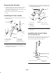
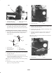
1. Remove the retainer securing the end of the boom
supply hose connected to the tee located to the right of
the boom supply valves and disconnect it (Fig. 4).
m–6356
1
2
3
8-3/4 inches (22.2 cm)
4
Figure 4
1. Boom supply valves
2. Boom supply hose
3. Disconnect here
4. Flow meter
2. Cut the boom supply hose 8-3/4 inches (22.2 cm) to the
right of the flow meter (if equipped) or 32 inches
(81 cm) from the supply tee (located directly behind the
boom valves) using a hacksaw (Fig. 4). Remove the
hose clamp from the loose end and discard the hose and
fitting.
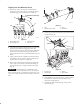
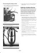
3. Apply a liberal amount of liquid soap to the barb of the
large fitting and to the inside of the hose coming from
the flow meter or supply tee as applicable.
4. Slide a large ratcheting hose clamp (removed from the
hose in step 2) over the hose and install the fitting all
the way into the hose, securing it with the hose clamp
(Fig. 5).
Important The fitting may be very difficult to push
into the hose. It is very important, however, that you get it
all the way into the hose, ensuring that it will not leak. You
may need to remove the hose from the machine at the flow
meter.
m–6375
1
2
3
4
Figure 5
1. Hose
2. Ratcheting hose clamp
3. Fitting
4. Flow divider
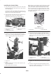
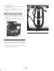
5. Cut the by-pass hose half way between the boom valves
and the tank (Fig. 6).
m–6380
1
2
4
3
2
Figure 6
1. By-pass hose
2. S53 tee fitting
3. S53 tee
4. Small retainer
6. Using liquid soap on the barbs, insert an S53 tee fitting
into each hose end and secure them using 2 large,
plastic hose clamps (Fig. 6).
7. Assemble the S53 tee to the fittings, using 2 small
retainers (Fig. 6).