Form No. 3372-927 Rev C Pro Control™ XP Spray System Multi-Pro® 5800 Turf Sprayer Model No. 41604—Serial No. 311000476 and Up Register at www.Toro.com.
Introduction and Note emphasizes general information worthy of special attention. WARNING CALIFORNIA Proposition 65 Warning Contents This product contains a chemical or chemicals known to the State of California to cause cancer, birth defects, or reproductive harm. Introduction .................................................................. 2 Safety ........................................................................... 3 Setup .....................................................................
Safety Read and understand the contents of this manual before operating the console computer. • Keep this document with the Operator’s Manual for the Multi Pro® 5800 Turf Sprayer. • It is very important that all who operate this equipment have ready access to these instructions at all times. • Read these instructions and the instructions in the Operator’s Manual for the Multi Pro® 5800 Turf Sprayer carefully. Be familiar with the controls and the proper use of the equipment.
Installation Loose Parts Use the chart below to verify that all parts have been shipped. Procedure 1 2 Description Use Qty. Mounting bracket Carriage bolt (5/16 x 3/4 inch) Locknut (5/16 inch) Computer console assembly Hand Knob Flowmeter Gasket Hose clamp, worm screw 1 3 3 1 2 1 1 1 Install the console computer. Install the flowmeter.
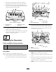
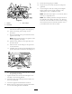
. Route the console computer cables from under the dashboard through the hole with the large grommet. 6. Plug the cables into their corresponding inputs on the rear of the console computer (Figure 3), and secure the cables by rotating the locking rings. 1 1 2 1 3 2 G013877 4 Figure 4 G017269 1. Bolts 2. Boom-valve-assembly Figure 3 Rear of console computer 1. Flowmeter cable connection 2. Speed sensor cable connection 3. Boom mount 4. Worm clamp 2.
1 2 11. Secure the locking rings if available. 1 12. Inspect all work to ensure that all hose clamps are tightened. 13. 13) Close bypass valves by rotating the red bypass knobs clockwise until a slight resistance is felt, indicating the valve is completely closed. Note: The knob may require 3 to 4 rotations (360=1 rotation) to completely close. G01 3879 Note: The numbers printed on the bypass knob are for reference only. Setting the knob to “0” does not ensure the valve is closed.
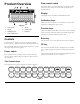
Flow-control switch Product Overview 3 1 2 This switch allows you to automatically or manually control the spray system. There are 2 automatic positions and 1 manual position. 4 Display The display shows the function and calibration data. Calibration keys G0 13881 5 6 These keys allow the operator to enter data into the console computer to calibrate the spray system. 7 Figure 8 1. Power switch 5. CE key 2. Display 6. Function keys 3. Calibration keys 7.
Keypad Reference Table Key Description Function* BOOM 1 CAL Length of boom 1 (1) It calculates the length of the boom by multiplying the number of nozzles by the spacing between them in inches (cm) of the left boom. 80 inches (204 cm) is set as the default. BOOM 2 CAL Length of boom 2 (2) It calculates the length of the boom by multiplying the number of nozzles by the spacing between them in inches (cm) of the center boom. 60 inches (152 cm) is set as the default.
Entering the Meter Cal Number Operation Use the gallon calibration number for US gallons per acre or US gallons per 1000 sq. ft. or a liter calibration number for liters per hectare. The console computer automatically controls the spray application rate for varying vehicle speeds. You set the target volume per unit area to spray and the console computer automatically maintains the flow within the proper range of the vehicle speed and continually displays the actual volume of material per area sprayed.
Self-Testing the Console Computer 8. Press the [Enter] key. Note: You have now completed programming the console computer. The flashing CAL in the display should stop. If not, repeat the procedures for programming the console computer. The self test allows you to simulate the speed for testing the system when the vehicle is not moving. 1. Press the [Self Test] key. Displaying Data 2. Press the [Enter] key. To display the following data, do the following: 3. Enter the speed in mph or km/h.
Setting the Power Down Delay Time will clear itself when the speed sensor detects that the vehicle is in motion. A speed calibration value greater than or equal to 900 (US or TU) or 230 (SI) is recommended when operating in this mode. To conserve the 12-volt battery on the vehicle, set the power down delay. In this power down mode, all the data is retained but the time of day clock does not operate. The power down day is initially set to 10 days. 1. Press the [Time] key 5 times.
6. Ensure that the Boom 1, Boom 2, and Boom 3 switches are in the On position. 7. Set the Man/Rate switch to Rate 1. 8. Increase or decrease the vehicle speed by 1 mph (2 km/h). Note: The system should automatically correct the target application rate. If the system does not correct the application rate, review the Initial System Setup; then refer to Troubleshooting. 9. After spraying a swath, switch the foot switch to the Off position to shut off the spray flow to all booms.
Maintenance Recommended Maintenance Schedule(s) Maintenance Service Interval Maintenance Procedure • Clean the flowmeter (More often when using wettable powders). Every 200 hours • Calibrate the flowmeter. Yearly Cleaning the Flowmeter 9. Use a low pressure (50 kPa or 5 psi) air jet to ensure that the turbine spins freely. If it does not spin freely, loosen the hex stud on the bottom of the turbine hub by 1/16 of a turn until the turbine spins freely. Service Interval: Every 200 hours 1.
4. 5. 6. 7. 8. 9. 10. 11. 12. 10. Enter the new Speed Cal number using the Entering the Speed Cal Number procedure. Press the [Enter] key. Press the [Boom 2 Cal] key. Press the [Enter] key. Enter 60 (US or TU) or 152 (SI). Press the [Enter] key. Press the [Boom 3 Cal] key. Press the [Enter] key. Enter 80 (US or TU) or 204 (SI). Press the [Enter] key. Entering the Valve Cal Number The Valve Cal number controls the response of the spray system to meet the changes of the vehicle speed.
Calibrating the Flowmeter Testing the Flowmeter Cable Service Interval: Yearly—Calibrate the flowmeter. 1. Disconnect the console control cable from the flowmeter cable. 1. Press the [Meter Cal] key. 2. Hold the cable so that the keyway is in the 12 o’ clock position (Fig. Figure 12). 2. Press the [Enter] key. 3. Enter the Meter Cal number. Note: The Meter Cal (or flowmeter) calibration number is stamped on the tag attached to the flowmeter or meter cable (Figure 10). 4 4. Press the [Enter] key.
Troubleshooting Note: If the console computer malfunctions or needs repair, you can resume spraying in manual mode by unplugging the cables from the rear of the console computer. You can then control the system using the center console controls. Problem The display lights do not illuminate when the power turned On. Possible Cause Corrective Action 1. The fuse on the back of the console computer is blown. 1. Replace the fuse. 2. The battery connections are loose. 3.
Problem The rate indication that is displayed is inaccurate or unstable. Possible Cause 1. You incorrectly entered a number in the console computer. 1. Verify that all the numbers entered in the console computer are correct. 2. The wheel drive setting is not set to SP3. 3. The Speed Cal number is incorrect. 4. The Rate 1 or Rate 2 display is not constant when the speed is constant. 2. Set the wheel drive setting to SP3. 5.
Notes: 18
Notes: 19