
Installation Instructions
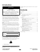


5.Routetheconsolecomputercablesfromunderthe
dashboardthroughtheholewiththelargegrommet.
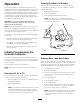
6.Plugthecablesintotheircorrespondinginputsonthe
rearoftheconsolecomputer(Figure3),andsecurethe
cablesbyrotatingthelockingrings.
G017269
1
2
Figure3
Rearofconsolecomputer
1.Flowmetercable
connection
2.Speedsensorcable
connection
7.Assemblethecomputerconsoletothemounting
bracketwith2handknobs(Figure2).
8.Adjustthepivotangleoftheconsolefacetothedesired
position,andtightenthehandknobsoneitherside
consoletosecuretheposition.
2
InstallingtheFlowmeter
Partsneededforthisprocedure:
1Flowmeter
1
Gasket
1Hoseclamp,wormscrew
Procedure
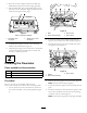
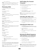
Movetotherearofthemachineandlocatethe
boom-valve-assemblyontheboom-valvemountingbracket.
1.Loosen,butdonotremove,theboltsthatsecurethe
boom-valve-assemblytothemountingbracket(
Figure
4).
G013877
1 2 1
3
4
Figure4
1.Bolts3.Boommount
2.Boom-valve-assembly4.Wormclamp
2.Loosentheexistingwormclampthatsecuresthe
agitationvalvetotheboom-valve-assembly(Figure4).
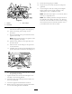
3.Carefullymovetheboom-valve-assemblyawayfrom
theagitationvalve(Figure5).
G013878
1 2
3
Figure5
1.Gasket
3.Wormclamp
2.Boom-valve-assembly
4.Removetheexistinggasketinthevalvebody(Figure5).
Note:Retainboththeclampandgasket.
5.Locatetheowmeter,gasket,andwormclampinloose
parts.
6.Installtheowmeterin-linebetweentheagitationand
boomvalveassemblieswiththeowarrowpointing
towardthe3boomvalves(
Figure6).
Note:Ensurethatbothgasketsareproperlyinstalled.
5