
Installation Instructions


G01 3879
1
2
1
3
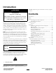
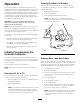
Figure6
1.Gasket
3.Wormclamps
2.Flowmeter
A.Installtheexistinggasketintotheowmeterside
thatwillmatewiththeagitationvalve(Figure6).
B.Installtheexistingwormclampoverthe
owmeter.
C.Movetheowmeterintopositionushwiththe
agitationvalvebody.
Note:Securetheowmetertotheagitationvalve
bodybytighteningtheclamp.
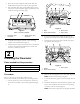
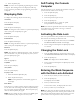
D.Installthenewgasketintotheopensideofthe
owmeterbody.
E.Installthenewwormclampovertheopenend
oftheowmeter.
F.Carefullymovetheboom-valve-assemblyintothe
positionushwiththeowmeterbody(Figure7).
G013880
Figure7
G.Securetheowmetertotheboom-valve-assembly
bytighteningtheclamp.
7.Tightentheboltsthatsecuretheboombypassvalve
assemblytothemountingbracket.
8.Locatethespraysystemwiringharnessroutedtothe
boomvalvemanifold.
9.Locatethecappedroundowmeterconnector.
10.Removethecaptoexposethe3-pinplugandconnect
ittothewirecomingfromtheowmeter.
11.Securethelockingringsifavailable.
12.Inspectallworktoensurethatallhoseclampsare
tightened.
13.13)Closebypassvalvesbyrotatingtheredbypass
knobsclockwiseuntilaslightresistanceisfelt,
indicatingthevalveiscompletelyclosed.
Note:Theknobmayrequire3to4rotations(360=1
rotation)tocompletelyclose.
Note:Thenumbersprintedonthebypassknobare
forreferenceonly.Settingtheknobto“0”doesnot
ensurethevalveisclosed.Youmustcontinueturning
theknobuntilyoufeelrotationalresistance—thisis
yourindicationthatthevalveisclosed.
6