
Installation Instructions


ProductOverview
G0 13881
1
2
3
4
5
6 7
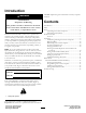
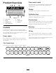
Figure8
1.Powerswitch
5.CEkey
2.Display6.Functionkeys
3.Calibrationkeys
7.Enterkey
4.Flow-controlswitch
Controls
TheProControl
™
Systemconsistsofacomputer-based
controlconsole,aspeedsensor,andaturbine-typeowmeter.
Becomefamiliarwiththecontrols(Figure8)beforeyoustart
theengineandoperatethesprayer.
Powerswitch
Thisswitchturnstheconsolepoweronandoff.Turning
offtheconsolecomputerdoesnotaffectthedatastoredin
thecomputer.
Flow-controlswitch
Thisswitchallowsyoutoautomaticallyormanuallycontrol
thespraysystem.Thereare2automaticpositionsand1
manualposition.
Display
Thedisplayshowsthefunctionandcalibrationdata.
Calibrationkeys
Thesekeysallowtheoperatortoenterdataintotheconsole
computertocalibratethespraysystem.
Functionkeys
Thesekeysdisplayneededdata,suchasthetotalareasprayed,
thetotalvolumeofmaterialsprayed,thevehiclespeed,and
thevolumeofmaterialremaininginthetank.
Enterkey
Thiskeyallowsyoutoenterdataintotheconsolecomputer.
CEkey
Thiskeyclearsthedatashowninthedisplay;italsoenables
youtotogglethroughtheoptionsfoundincertainfunction
keys.
Theconsolecomputerallowsthefollowingparameters:Area:
US(acres);SI(hectares)orTU(1000ft
2
).
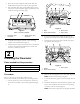
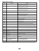
TheConsolekeys
ThekeypadfortheconsolecomputerisshowninFigure9.
G013305
BOOM 1
CAL
1
BOOM 2
CAL
2
BOOM 3
CAL
3
SPEED
CAL
4
METER
CAL
5
VALVE
CAL
6
RATE 1
CAL
7
RATE 2
CAL
8
VOL
TANK
9
TIME
0
SELF
TEST
CE
TOTAL
AREA
TOTAL
VOLUME
FIELD
AREA VOLUME
FIELD
DISTANCE
SPEED
MIN
VOL /
HOUR
AREA /
MENU
DATA
ENTER
Figure9
7