
Installation Instructions

G014028
1
2
3
4
5
6
7
8
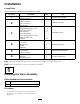
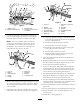
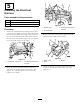
Figure17
1.Bolt,batterypost5.Negativebatterypost
2.Fuse,50amp6.Battery
3.Fuseholder,electrichose
reelharness
7.Locknut,batterypost
4.Electrichosereelharness8.Positivebatterypost
5.Connectthenegative,blackringterminaltothe
negativebatterycable(Figure17).
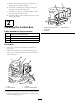
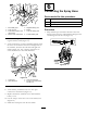
6.Atthecontrolbox,routetheremainingharnesswith
thehosereelconnectorforwardontherightsideof
themachine,betweenthetankskidandrightrear
fender(
Figure18).Use2pushinconnectorsto
securetheharnesstothetankskidframe.
G014135
1
2
3
4
Figure18
1.Controlbox
3.Hosereelconnector
2.Tankskidframe
4.Electrichosereelharness,
shorterend
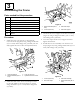
7.Connecttheharnesstothehosereel.
8.Atthebattery,installthefuseintotheopen
connectorintheharness(Figure17).
9.Replacethebatteryterminalcoversandinstallthe
batterycover.
10.Usethestraptosecurethecovertothebatterybox
(Figure16).
11.Installthe10ampfuseintothefuseblock.
6
ConnectingtheSprayHose
Partsneededforthisprocedure:
1
Longhosewithtting
1
Spraygun
1Hoseclamp,small
Procedure
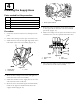
1.WrapTeontapearoundthethreadsofthehose
ttingonthelonghoseandinstallthettingintothe
connectingtubeonthereel(Figure19).
Figure19
10