
Installation Instructions
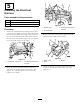

Installation
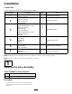
LooseParts
Usethechartbelowtoverifythatallpartshavebeenshipped.
ProcedureDescription
Qty.
Use
Hosereelvalveassembly4
1
Bolt(M8X260mm)
2
Installthevalveassembly.
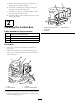
Controlboxandbracketassembly
1
Bolt(1/4x5/8inch)
3
Locknut(1/4inch)
3
2
ReducerFitting1
Installthecontrolbox.
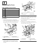
Hosereelsupport1
Flange-headbolt(3/8x1inch)
10
Flangenut(3/8inch)
10
Hosereelstrap2
Hosereelassembly1
Flange-headbolt(5/16x1inch)
1
Flangenut(5/16inch)
1
3
Cabletie
10
Assembletheframe.
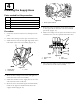
Hose1
Hoseclamp2
Straightbarb
1
Conduit
1
4
Cableties
2
Installthesupplyhose.
Plastictie4
Fuse,50Amp1
5
Pushinconnector2
Installtheelectricalharness
Longhosewithtting
1
Spraygun
1
6
Hoseclamp,small1
Connectthesprayhose.
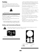
Note:Determinetheleftandrightsidesofthemachinefromthenormaloperatingposition.
Note:Threadsealingtapeisusedintheinstallationofthiskit.
1
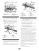
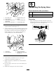
InstallingtheValveAssembly
Partsneededforthisprocedure:
4Hosereelvalveassembly
2
Bolt(M8X260mm)
Procedure
1.Loosen,butdonotremove,theboltssecuring
theboomvalveassemblytothemountbracket
(
Figure3).
4