Form No. 3416-568 Rev A Tank Rinse Kit Multi-Pro 5800 Turf Sprayer Model No. 41614—Serial No. 401100000 and Up Installation Instructions WARNING Introduction This kit is designed to remove residual chemicals from a sprayer tank and affected hoses. It is a dedicated attachment for a turf spray application vehicle and is intended to be used by professional, hired operators in commercial applications. The information in this manual can help you and others avoid injury and product damage.
Safety • Always wash your hands and other exposed areas Read the safety and operation instructions in the machine Operator’s Manual. • Properly dispose of unused chemicals and Chemical Safety • Chemicals and fumes in the tanks are dangerous; as soon as possible after finishing the work. chemical containers as instructed by the chemical manufacturer and your local codes. never enter the tank or place your head over or in the opening.
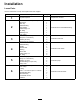
Installation Loose Parts Use the chart below to verify that all parts have been shipped. Procedure 1 2 3 4 5 6 Description Use Qty. No parts required – Hose—1.9 x 73.
Procedure 7 8 Description Use Qty. Delay timer Locknut (#10–24) Fuse (40 A) Relay Power relay Flange-head bolt (#10-24 x 1/2 inch) 3-position switch (with indicator light—2015 and before turf sprayers) 3-position switch (without indicator light—2016 and after turf sprayers) 1 2 1 1 1 2 No parts required – Install the delay timer and dash switch. 1 1 Finish the rinse tank kit installation.
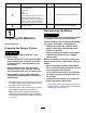
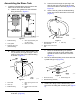
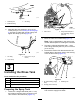
2 Preparing the Rinse Tank Parts needed for this procedure: 1 Hose—1.9 x 73.7 cm (3/4 x 29) 1 Rinse tank 1 Tank cap 1 Bulkhead fitting 1 Clear gasket 1 Plastic flange nut 1 90° fitting 1 Retaining fork 1 Hose clamp g014029 Figure 2 1. Battery cover 3. Buckle 2. Strap Cutting the Hose 1. Measure 20.3 cm (8 inches) from the end of the hose 1.9 x 73.7 cm (3/4 x 29) and mark that location (Figure 4). g029414 Figure 3 1. Positive battery cable 3. Negative battery post 2.
Assembling the Rinse Tank 1. D. Lower the wire through the opening in the tank fill hole and route it through the open hole at the bottom of the tank (Figure 5 and Figure 6). E. Use the wire to guide the bulkhead fitting to the open hole at the bottom of the tank (Figure 7). Install the bulkhead fitting into the hole at the bottom of the rinse tank as follows: A. Install a clear gasket onto the bulkhead fitting as shown in Figure 5. g206390 Figure 5 g014229 1. Bulkhead fitting 4.
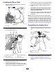
g014260 Figure 9 1. Retaining fork 3. 90° fitting 2. Bulkhead fitting 4. 5. Rotate the fitting so that it faces rearward. Assemble the hose segment—53.3 cm (21 inches) that you cut in Cutting the Hose (page 5) onto the 90° fitting with a hose clamp, and tighten the clamp by hand (Figure 9). g206427 Figure 11 1. Valve mount 2. 2. Flange-head bolt (3/8 x 1 inch) and flange locknut (3/8 inch) Move the valve mount rearward (Figure 11).
Installing the Rinse Tank 1. Assemble the rinse tank onto the machine as shown in Figure 13. 5. Repeat steps 2 through 4 for the other hold down at the other recess in the rinse tank (Figure 14). 6. Carefully tighten the bolts and flange nuts by hand. Important: The rinse tank must be seated and secure, but the hold down should not deform or warp the tank. 7. Replace the supply hose at the rear of the tank and secure it with the retaining fork removed previously.
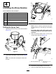
4 Installing the Rinse Nozzles Parts needed for this procedure: 2 Rinse nozzle 2 Bulkhead fitting 1 Gasket 2 Shoulder bolt 2 Bushing 2 Rinse vane 2 Plastic flange nut 2 90° fitting g206492 Figure 17 1. Drill marks 3. Note: Place a container inside the tank below the areas where you are drilling to catch falling debris. Drilling the Spray Tank 1. Move to the drill mark behind the tank lid. Open the tank lid and remove the strainer basket (Figure 16).
7. Repeat steps 4 through 6 at the forward drill mark (Figure 19). g207947 Figure 20 1. Gasket 4. Bushing 2. Bulkhead fitting 5. Rinse vane 3. Rinse nozzle 6. Shoulder bolt 2. Assemble the rinse vane, bushing, and shoulder bolt onto the rinse nozzle (Figure 20). 3. Apply PTFE thread sealant to the threads of the rinse-nozzle. 4. Install the rinse-nozzle assembly into the bulkhead fitting and tighten by hand (Figure 20). 5. Assemble the gasket over the bulkhead fitting (Figure 20). 6.
Installing the Rinse Nozzles Owner provided material: PTFE sealant 1. Working inside the tank through the 41 cm (16 inch) opening, align the nozzle assembly up through the 4.5 cm (1-3/4 inch) hole that you drilled in Drilling the Spray Tank (page 9)as shown in Figure 21. g206557 Figure 22 3. Rinse-nozzle assembly 1. Plastic flange nut 2. Hole 4.5 cm (1-3/4 inch)—forward g206558 4. Apply PTFE thread sealant to the threads of the both 90° fittings. 5.
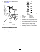
5 Installing the Rinse-Tank Pump Parts needed for this procedure: 1 Rinse-tank pump 4 Bolt (1/4 x 1-3/4 inches) 4 Washer (1/4 inch) 4 Serrated-flange nut (1/4 inch) 1 Pump cover g206594 Assembling the Pump to the Machine Owner provided material: PTFE sealant 1. Align the holes in the mounting-flange spacers of the rinse-tank pump with the holes in the saddle plate of the tank frame (Figure 24). g219470 Figure 24 1. Washer (1/4 inch) 4. Serrated-flange nut (1/4 inch) 2.
6 Installing the Hoses and Filter Parts needed for this procedure: g219471 Figure 25 1. 2-socket electrical connector—machine harness (RINSE PUMP) 5. 2. 2 pin connector (rinse-tank pump harness) Plug the 2 pin connector of the rinse-tank pump harness into the 2-socket of the machine harness labeled RINSE PUMP (Figure 25). 2 Hose—1.9 x 61 cm (3/4 x 24 inches) 9 Hose clamp 1 T-fitting 1 Hose—1.
3. 4. Installing the Hoses and Filter Assemble the hoses—1.9 x 180 cm (3/4 x 71 inches) and a hose clamp onto the T-fitting as shown in Figure 27. 1. Tighten the 3 hose clamps that secure the 3 hoses to the T-fitting by hand. Assemble the hose—53.3 cm (21 inches) at the bottom of the rinse tank onto the inboard straight-barb fitting of the rinse-tank pump with a hose clamp, and tighten the clamp by hand (Figure 27).
g206824 Figure 31 1. Hose clamp 3. Hose—1.9 x 180 cm (3/4 x 71 inches) 2. Straight-barb fitting (outlet—filter) g219997 5. Adjust the position of the filter head so that the bowl of the filter assembly is vertical and tighten the 2 hose clamps by hand (Figure 30 and Figure 31). 6. Assemble the split convoluted tubing over the hose—43.3 cm (17 inches) between the rinse tank and the rinse-tank pump and secure the tubing with 2 tie wraps (Figure 32). Figure 30 1.
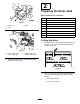
Installing the Rinse-Pump Cover Insert the 2 tabs of the rinse-pump cover into the 2 slots in the saddle plate of the tank frame (Figure 33). A. Install the delay timer to the location shown in Figure 34 or Figure 35 with the locknut from the electrical panel. B. Connect the timer to the 2-socket connector labeled delay timer of the machine wire harness (Figure 34 or Figure 35). g219998 Figure 33 1. Tab (rinse-pump cover) 2. Slots (saddle plate) 7 g015113 Figure 34 2014 and Before Machines 1.
g219469 Figure 36 2016 and After Machines 1. Fuse (40 A) 5. Flange-head bolt (#10-24 x 1/2 inch) 2. Fuse block 6. Power relay (4-pin) 3. Locknut (#10-24) 7. 4-socket connector (machine wire harness) g035435 Figure 35 2015 Machines 1. Fuse block 7. Locknut (#10–24) 2. Fuse (40 A) 8. 5-socket connector (machine wire harness) 3. Bolt and nut (electrical panel) 9. Relay (5-pin) 4. 2-pin connector (delay timer) 10. 4-socket connector (machine wire harness) 5.
Installing the Rocker Switch into the Dash 1. Remove the plug for the rinse tank switch from the dash panel (Figure 37 or Figure 38). Note: It is the second plug to the right of the ignition key. g034585 Figure 38 2016 and After Machines 1. Plug 3. 3-position switch (without indicator light) 2. Connector for rinse tank (main wire harness) g034584 Figure 37 2015 and Before Machines 1. Plug 3. 3-position switch (with indicator light) 2. Connector for rinse tank (main wire harness) 18 2.
8 Connecting the Battery No Parts Required Procedure WARNING g207211 Figure 39 Electrical sparks can cause the battery gasses to explode, resulting in personal injury. 1. Battery cover 4. Negative battery post 2. Positive battery cable 5. Negative battery cable Incorrect battery cable routing could damage the sprayer and cables causing sparks. 3. Positive battery post • Always disconnect the negative (black) battery cable before disconnecting the positive (red) cable. 2.
Operation Operating the Rinse Kit Using the Rinse Kit will result in a rinsate (a diluted solution of residual chemicals). In many cases, it is appropriate to apply the rinsate onto a treated area(s). However, before doing so, check with the chemical manufacturer to ensure that the application of a diluted solution to the treated area(s) does not adversely affect the performance of the product.
Note: If you are operating a 2015 and before 1. machine, the light on the 3-position switch will illuminate to indicate that the pump is running. Turn on the rinse-tank pump by performing 1 of the following: • Press up 3-position switch for a timed rinse. After 110 seconds, the pump stops running. • Press and hold down the 3-position switch for a desired duration.
Maintenance Inspecting the Rinse System for Leaks and Damage Inspect the Filter Service Interval: After the first 5 hours Service Interval: Before each use or daily—Inspect the hoses for leaks. Every 50 hours 1. After the first 5 hours—Inspect hoses for damage. Rotate the filter counterclockwise to remove the bowl from the filter head (Figure 42). Every 100 hours—Inspect hoses and O-rings for damage Contact your Authorized Toro Dealer to obtain replacement parts.
until the hold downs are snug against the rinse tank (Figure 43). Storage Note: Do not overtighten the bolt(s) and locknut(s) of the hold down(s), or deform the tank. Storing the Machine in Above-Freezing Temperatures Less than 30 Days Important: Overtightening the tank strap fasteners can deform and damage the hold downs.
Notes:
Notes:
Notes:
European Privacy Notice The Information Toro Collects Toro Warranty Company (Toro) respects your privacy. In order to process your warranty claim and contact you in the event of a product recall, we ask you to share certain personal information with us, either directly or through your local Toro company or dealer. The Toro warranty system is hosted on servers located within the United States where privacy law may not provide the same protection as applies in your country.
The Toro Warranty A Two-Year Limited Warranty Conditions and Products Covered The Toro Company and its affiliate, Toro Warranty Company, pursuant to an agreement between them, jointly warrant your Toro Commercial product (“Product”) to be free from defects in materials or workmanship for two years or 1500 operational hours*, whichever occurs first. This warranty is applicable to all products with the exception of Aerators (refer to separate warranty statements for these products).