
Installation Instructions

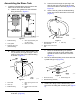


InstallingtheRinseTank
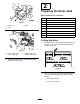
1.Assembletherinsetankontothemachineas
showninFigure13.
g206448
Figure13
1.Rinsetank
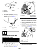
2.Aligntheholddownwiththerecessinthetopof
therinsetank(Figure14).
g206469
Figure14
1.Bolt(3/8x1-1/2inches)4.Flangelocknut(3/8inch)
2.Washer(3/8inch)
5.Valvemount
3.Holddown(rinsetank)6.Recess(rinsetank)
3.Aligntheslotintheholddownwiththeholein
thevalvemount(Figure14).
4.Looselyassembletheholddowntothevalve
mountwithabolt(3/8x1-1/2inches),2washers
(3/8inch),andaangelocknut(3/8inch).
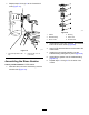
5.Repeatsteps2through4fortheotherholddown
attheotherrecessintherinsetank(Figure14).
6.Carefullytightentheboltsandangenutsby
hand.
Important:Therinsetankmustbeseated
andsecure,buttheholddownshouldnot
deformorwarpthetank.
7.Replacethesupplyhoseattherearofthetank
andsecureitwiththeretainingforkremoved
previously.
Note:Oncetherinsetankhasbeeninitiallylled,
checktheholddownsandtherinsetankforplay(the
weightofthewaterinthetankcanfurtherseatthe
tankagainsttheframe).Ifneeded,tightenthebolt(s)
andangelocknut(s)untiltheholddownsaresnug
againsttherinsetank—donotdeformthetank;refer
toInspectingtheRinseTankHoldDowns(page22).
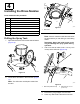
AssemblingtheSupplyHose
1.Alignthe90°barbedttingofthesupplyhose
withthehousingforthesuctionscreen(Figure
15).
g206490
Figure15
1.90°barbedtting(supply
hose)
3.Retainingfork
2.Housing(suctionscreen)
2.Securethe90°barbedttingtothehousing
(Figure15)withtheretainerforkthatyou
removedinstep4ofPreparingtheSprayTank
(page7).
8