
Installation Instructions

InstallingtheRinseTank
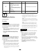
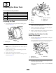
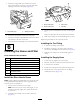
1.InstalltherinsetankasshowninFigure9.
G014233
1
Figure9
1.Rinsetank
2.Installtherinse-tankstrapstothehardwareinstalled
previouslyontherearstraptankstraps.
Note:Thewiretanklidstopneedstobeinstalledover
theleftrinse-tankstrapandthemaintankstrap;then
securedwiththelocknut.
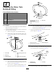
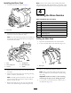
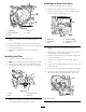
G014234
1
2
3
4
5
6
6
3
Figure10
1.Bolt
4.Carriagebolt
2.Tanklidstopwire5.Rinse-tankstrap
3.Locknut6.Washer
3.Securetherinse-tankstrapstothereartankstrapwith
2locknuts.
4.Securetherinse-tankstrapstothemountingrailusing
2bolts,4washers,and2locknuts.
Note:Carefullytightenthefasteners.Therinsetank
mustbeseatedandsecurebutthestrapsshouldnot
deformorwarpthetank.
5.Replacethesupplyhoseattherearofthetankand
secureitwiththeretainingforkremovedpreviously.
Note:Oncetherinsetankhasbeeninitiallylled,check
andtightentherinse-tankstrapfasteners,ifnecessary,asthe
weightoftheliquidcanfurtherseatthetankagainsttheframe.
4
InstallingtheRinseNozzles
Partsneededforthisprocedure:
2Rinsenozzle
2
Bulkheadtting
2
Shoulderbolt
2Bushing
2Rinsevane
2
Gasket
2
Plasticangenut
2
90°tting
DrillingtheMainTank
1.Openthetanklidandremovethestrainerbasket.
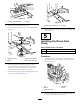
2.Locatethe2drillmarksinthemaintank(Figure11).
G014244
1
Figure11
1.Drillmarks
3.Movetothedrillmarkbehindthetanklid.
Note:Placeareceptacleinsidethetank,belowthe
areastobedrilled,tocatchanydebriscreatedduring
thecutting.
Important:Debrisleftinsideatankcouldclog
anddamagethespraysystemduringoperation.
4.Usea4.5cm(1-3/4inch)holesawtodrillaholeat
thedrillmark(Figure12).
6