
Installation Instructions

G014245
1
2
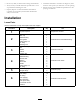
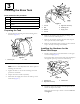
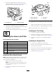
Figure12
1.Holesaw2.Drillmark,behindthelid
5.Afterdrillingthehole,removeanyroughedgesinthe
cut.
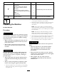
6.Removeanydebristhatenteredthemaintankduring
thecuttingprocess.
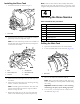
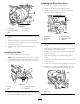
7.Movetothedrillmarkinfrontofthetanklidand
repeattheprocedurefortheforwardhole(Figure13).
G014248
1
2
Figure13
1.Holesaw
2.Drillmark,infrontofthelid
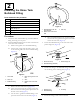
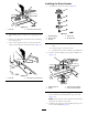
InstallingtheRinseNozzles
1.AssemblethenozzlesasshowninFigure14.
G014252
2
4
3
5
1
Figure14
1.Bulkheadtting
4.Rinsevane
2.Rinsenozzle
5.Shoulderbolt
3.Bushing
A.Installarinsevaneandbushingovertheshoulder
bolt.
B.Installallpartstotherinsenozzle.
C.Installtherinse-nozzleassemblytothebulkhead.
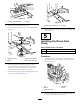
2.Installanozzleassemblyupthroughthedrilledhole
(Figure15).
G014246
1
3
4
2
Figure15
1.Plasticangenut3.Hole(previouslydrilled)
2.Gasket
4.Rinse-nozzleassembly
3.Installthegasketandplasticangenutoverthe
exposedthreadsofthebulkheadontopofthetank
(Figure15).
Note:Ensurethatthesealisseatedcorrectlybetween
theplasticnutandthetanksurface.
4.Installthe90°ttingintothethreadedopeningofthe
rinsenozzlebulkhead(Figure16).
7