
Installation Instructions

G014247
1
2
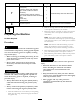
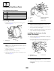
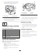
Figure16
1.Assemblynozzlebulkhead
2.90°tting
5.Movetotheforwardholeinthetank.
6.Installanozzleassemblyupthroughthedrilledhole
(Figure17).
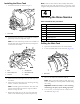
G014249
1
3
4
2
Figure17
1.Plasticangenut3.Hole(previouslydrilled)
2.Gasket
4.Rinse-nozzleassembly
7.Installthegasketandplasticangenutoverthe
exposedthreadsofthebulkheadontopthetank
(Figure17).Ensurethatthesealisseatedcorrectly
betweentheplasticnutandthetanksurface.
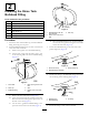
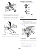
8.Installthe90°ttingintothethreadedopeningofthe
rinse-nozzlebulkhead(Figure18).
G014250
1
2
Figure18
1.Assemblynozzlebulkhead
2.90°tting
9.Alignthehosebarbofthe90°ttingstotherightside
ofthemachine.
5
InstallingtheRinse-Tank
Pump
Partsneededforthisprocedure:
1Rinse-tankpump
2
Straightttings
Procedure
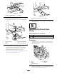
1.Assembletherinse-tankpumptothetankframeon
theplatformattherearrightsideofthemaintankas
showninFigure19.
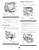
G014251
1
2
3
4
5
Figure19
1.Bolt
4.Tankframe
2.Washer5.Locknut
3.Rinse-tankpump
2.Securetherinse-tankpumptotheframeusing4bolts,
4washers,and4locknuts(Figure19).
8