Form No. 3368-972 Rev D Ultra Sonic Boom™ Kit Multi-Pro® 5800 Turf Sprayer Model No. 41615—Serial No. 311000001 and Up Installation Instructions This attachment maintains consistent distances from the boom nozzles to the ground when spraying over uneven surfaces and is intended to be used by professional, hired operators in commercial applications. It is primarily designed for spraying golf course applications, parks, sports fields, and on commercial grounds.
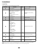
Installation Loose Parts Use the chart below to verify that all parts have been shipped. Procedure 1 2 3 4 5 6 7 8 Description Use Qty.
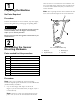
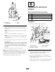
other set is for a covered boom. You will have one set of 2 angled straps (either for the covered boom or for the uncovered boom) that you will not use on the machine. 1 Preparing the Machine Note: The top straps for the uncovered booms also serve as the bottom straps for the covered booms. No Parts Required 4 Procedure 3 Position the machine on a level surface, stop the engine, remove the ignition key, and engage the parking brake.
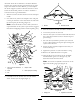
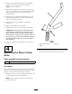
3 2 1 G017129 3 4 Figure 2 For covered booms only 1. Hinge (2) 3. Bushing (8) 2. Angled strap (2) 4. Bottom strap Figure 3 Hardware for a covered boom shown 2. Insert the bushings into the welded tube openings in the hinges and straps as shown in Figure 1 or Figure 2. 1. Hex-head bolt 4. Springs 2. Flat washer 5. Locknuts (5/16 inch) 3. Welded tube opening 5. Install a flat washer on the exposed end of each of the bolts. 6. Install a spring on the end of each bolt (Figure 3). 7.
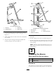
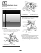
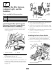
1 ultrasonic boom kit to maintain a consistent distance between the nozzles and the ground when the ground slopes downward from the machine, you must adjust the boom support system to allow the booms to travel below the horizontal position in order to maintain a constant nozzle-to-ground distance. 1. Raise the booms and have them rest in the transport cradle. 2. For each boom, remove the hairpin cotter and pull out the pin from the rod to disconnect the rod from the boom pivot pin housing (Figure 4).
12. Remove the hydraulic block from the mounting bracket by removing 2 bolts and 2 locknuts. Note: Save the hardware. 13. Remove the 2 hydraulic connectors from the ports and the gauge port from the old hydraulic manifold block, and install them on the new hydraulic manifold block. 1 14. Install the new hydraulic manifold block onto the mounting bracket with the 2 bolts and 2 locknuts that you previously removed. 15. Tighten the gauge port and the 2 hydraulic connectors. 2 16.
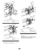
5 Installing the Sonic Boom Sensors 2 Parts needed for this procedure: 2 Sonic boom sensor 2 Bracket G017148 1 2 Programming plug 2 Sensor cover 2 Lower sensor housing 2 Cap tube 2 Sensor guard bracket 2 Sensor cable (4 m) 4 Large nut 6 U-bolt 8 Locknut (1/4 inch) 8 Bolt (5/16 x 3/4 inch) 4 Bolt (5/16 x 1-1/4 inch) 12 Locknut (5/16 inch) 12 Cable tie Figure 9 Rear view 1. Mounting bracket (2) 2. Locknuts (1/4 inch) (12) 2.
1 2 6 3 4 3 5 G017150 7 8 2 1 Figure 11 For a covered boom only 1. Sensor guard bracket 2. Hinge (of sensor mounting hardware) G017151 Figure 13 Uncovered boom configuration shown 1. Cover 5. Cap tube 2. Sensor 6. Bolts (5/16 x 1-1/4 inch) 3. Large nut 7. Locknuts (5/16 inch) 4. Lower sensor housing 8. Finished sensor assembly G017157 1 5. Install the programming plug on the sensor (Figure 14).
6 Mounting the Electronic Control 1 2 Parts needed for this procedure: 3 4 1 Electronic controller 1 Mounting bracket 4 Bolt (1/4 x 1-1/8 inch) 4 Locknut (1/4 inch) G017158 Figure 14 1. Sideways “T” 3. Notch Procedure 2. Arrows aligned 4. Sensor 1. Remove the knockout plug (Figure 15). 3 6. Insert the sensor into the lower sensor housing, and secure it with 2 large nuts provided with the sensor (Figure 13). 4 1 5 2 Note: Discard the lock washers that come with the sensors. 7.
7 Installing the Wire Harness, Indicator Light, and the Switches Parts needed for this procedure: 1 Wire harness 1 Rocker switch 1 Indicator light 12 Cable tie Figure 17 1. Ground terminal block 2. Fuse block 4. Secure the ground terminal on the wire harness to the ground terminal block (Figure 17). Connecting the Wire Harness to the Electronic Controller, Ground Block, Main Power Source, and Battery 5.
2 3. Insert the rocker switch in the dashboard opening. 3 1 4. Connect the switch connector on the wire harness to the switch. 4 Installing the Indicator Light and Connecting the Switches 1. Remove the right-hand side cover on the center console by removing 5 bolts and a long screw. 2. Disconnect the connections from the 2 existing boom lift switches that control the left-hand and right-hand booms. Note: Tuck the connectors from the old wire harness away. 3.
8 Calibrating the Sonic Booms No Parts Required Procedure In this procedure, you will have 20 seconds to calibrate the sensors on the booms. The distance you set between the sensor on each boom and the ground after the 20-second calibration period is the boom height setting in automatic mode until the next time you calibrate the sensor.
Operation Using the Controls • On momentarily: The light comes on when you activate the sonic boom system. The light will turn off after a few seconds and remain off as long as the system is operating properly. The Sonic boom switch is located on the dashboard and has 2 settings: Automatic and Manual. • Flashing: There is an active fault in the sonic boom system.
Maintenance Cleaning Clean the sensors periodically with a damp cloth. If a sensor is damaged or excessively dirty, replace it. Important: Do not spray water at or on the sensors. Water sprayed under even household pressure can damage the sensor. Always cover the sensors completely before washing the sprayer. Note: When the booms are in the cradle for extended periods of time, the seal around each sensor (which is oriented upward) may become exposed to ultraviolet light and gradually deteriorate.
Troubleshooting Note: Refer to the service manual for additional diagnostic information. Problem One or both booms malfunction; the sonic boom light is Off. One or both booms malfunction; the sonic boom light flashes slowly. One or both booms are malfunctioning; the sonic boom light is on. Possible Cause Corrective Action 1. A fuse is blown. 1. Replace the fuse. 2. The light is burned out. 3. The electronic controller or wiring is damaged. 2. Replace the light. 3.
Schematics RIGHT CYL RETRACT TO RAISE LEFT CYL RETRACT TO RAISE C2 C3 C1 C4 9 7 S4 10 9 7 9 8 BOTTOM COIL S5 TOP COIL S3 S2 6 4 SH 4 8 TOP COIL BOTTOM COIL 3 OR LC G T P 5 VALVE S2 S2 (BOTT OM COIL) = C1 S1 (T OP COIL) = C2 VALVE S3 S2 (BOTT OM COIL) = C3 S1 (T OP COIL) = C4 G017133 Hydraulics (Rev.
G017138 Electrical (Rev.
Notes: 18
Notes: 19