
Operator's Manual


14
Operation
Note: Determine the left and right sides of the machine
from the normal operating position.
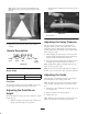
Controls
Become familiar with all the controls before you start the
engine and operate the line painter.
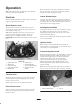
Speed Selector Lever
The speed selector has three speeds forward and one
reverse speed. To select speeds, move speed selector to
desired position. (Fig. 12).
Note: Before shifting gears into or out of reverse, the
traction control lever must be released. On–the–go
shifting may be accomplished between any of the
FORWARD speeds without releasing the traction control
lever.
2
1
3
4
5
6
7
8
Figure 12
1. Speed selector lever
2. Traction lever
3. Paint control lever
4. Paint control lever latch
5. Parking brake
6. Ignition switch
7. Castor release lever
(In front of right hand grip)
8. Optional hour meter
location
Traction Lever
To engage the traction drive, the lever must be pushed
forward against the right handgrip (Fig. 12). To stop
traction, release the lever.
Slowly squeeze the lever for gradual acceleration.
Paint Control Lever
Squeeze the lever against the left hand grip to start the
paint operation (Fig. 12). To stop the paint operation,
release the lever.
Paint Control Lever Latch
Rotate the latch over the paint control lever to lock the
lever in place (Fig. 12). Use lever latch when painting
long lines or when cleaning the system.
Castor Release Lever
To release the castor, squeeze the right lever against the
hand grip. Once the castor wheel has rotated, the lever can
be released. The castor will automatically lock when the
wheel returns to the straight position.
Parking/Service Brake
To engage the brake, move the lever rearward. To engage
the parking brake move the lever into the detent. To
disengage the parking brake, move the lever out of the
detent and forward (Fig. 12).
Always set the parking brake when you stop the machine
or leave it unattended.
Ignition Switch
Rotate the key to the ON position before starting the
engine with the recoil starter (Fig. 12). To stop the engine,
rotate the key to the OFF position.
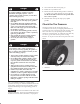
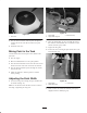
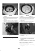
Pressure Regulator Knob
Regulates the paint pressure at the nozzle (Fig. 13) Loosen
the jam nut locking the knob. Adjust the knob in or out
until the desired paint pattern is attained. Rotating the
knob clockwise will increase the paint pressure,
counter–clockwise will decrease the paint pressure.
Tighten the jam nut to lock adjustment. Refer to the
Pressure Adjustment Section of this manual for correct
pressure settings.
Note: Excessive paint pressure will reduce the quality of
the line, create excessive over spray and reduce agitation.
1
2
Figure 13
1. Pressure regulator knob 2. Jam nut