
Operator's Manual


18
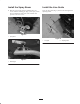
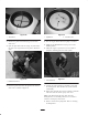
Note: Spray contact will cause paint buildup on the
shield that may drip or leave streaks when the paint is
shut off.
Figure 23
6. Tighten the screw when the desired spray width is
attained.
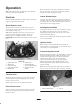
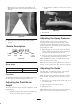
Nozzle Description
TJ60–8006 EVS
Nozzle
Series
Spray
Angle
Flow
Rate
Pattern Color
Code
Option
Figure 24
Spray Angle
2 in. – 4 in. line width 65_ Nozzle
4 in. + line width 80_ Nozzle
Flow Rate
The Flow Rate number represents the GPM of water at 40
psi. The higher the number the higher the flow rate.
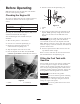
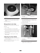
Adjusting the Paint Boom
Height
Thread the boom arm stop up or down to adjust the shield
height (Fig. 25).
• Adjust the height so the bottom of the shields are at
the top of the surface/grass to be painted.
• If the shields are positioned too low, they can leave
streaks.
1
Figure 25
1. Boom arm stop
Adjusting the Spray Pressure
The spray pressure may need to be adjusted when
changing nozzles, the mix ratio, paint brands or if the
temperature changes significantly. Increasing the spray
pressure will increase the volume and the velocity of the
paint exiting the nozzle.
1. While engaging the spray nozzle, rotate the pressure
regulator knob counterclockwise until a reduction in
the spray width and uniformity is observed.
2. Rotate the pressure regulator knob clockwise until an
acceptable spray width and pattern is achieved.
Note: Optimum line quality is normally attained at the
lower end of the pressure range.
Note: Excessive paint pressure will reduce the quality of
the line, create excessive over spray and reduce agitation.
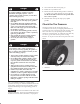
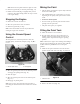
Adjusting the Guide
The guide (Fig. 26) allows the operator to stay aligned
with a string line or the existing painted line.
Note: The guide can be installed on the right or left side
of the machine, depending on the location of the paint
arm.
1. Loosen the screw securing the line marker (Fig. 26) to
the mounting tube.
2. Adjust the guide to the desired position.
3. Tighten the screw.
Note: When the paint arm is in the forward position, the
guide is not used and can be folded out of the way.