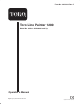
Form No. 3352-319 Rev. C Toro Line Painter 1200 Model No. 42004—250000001 and Up Operator’s Manual Register your product at www.Toro.
Operation . . . . . . . . . . . . . . . . . . . . . . . . . . . . . . . . . . Controls . . . . . . . . . . . . . . . . . . . . . . . . . . . . . . . . Starting the Engine . . . . . . . . . . . . . . . . . . . . . . . . Stopping the Engine . . . . . . . . . . . . . . . . . . . . . . . Using the Ground Speed Control . . . . . . . . . . . . . Mixing the Paint . . . . . . . . . . . . . . . . . . . . . . . . . . Filling the Paint Tank . . . . . . . . . . . . . . . . . . . . . . Mixing Paint in the Tank . . . . .
Introduction Read this manual carefully to learn how to operate and maintain your product properly. The information in this manual can help you and others avoid injury and product damage. Although Toro designs and produces safe products, you are responsible for operating the product properly and safely. Warning signals a hazard that may cause serious injury or death if you do not follow the recommended precautions. You may contact Toro directly at www.Toro.
• Never allow adults unfamiliar with these instructions to operate the machine. – Use a respirator or mask if there is a chance fumes may be inhaled. Read the instructions provided with the mask to insure proper protection is provided. • Never operate the machine while people (especially children) or pets are nearby. Stop the machine if anyone enters the area. – Do not use oil based paints. Use only latex based paint products.
Sound Pressure Level • If the machine should start to vibrate abnormally, stop the engine and check immediately for the cause. Vibration is generally a warning of trouble. This unit has an equivalent continuous A-weighted sound pressure at the operator ear of: 78 dB(A), based on measurements of identical machines per procedures outlined in Directive 98/37/EC and amendments. Slopes are a major factor related to slip and fall accidents which can result in a severe injury.
Safety and Instruction Decals Safety decals and instructions are easily visible to the operator and are located near any area of potential danger. Replace any decal that is damaged or lost. 93-7814 1. Entanglement hazard, belt—stay away from moving parts. 108-0326 108-0233 1. 2. 3. 4. 5. 6. Warning—read the Operator’s Manual. Fire hazard—stop the engine before fueling. Gear selector 7. Service/Parking brake On/Off switch 8. Locked Off 9. Engaged On 10. Disengaged 1. 2. 3. 4.
Specifications Note: Specifications and design subject to change without notice. General Specifications Engine Transaxle Kawasaki, 6 hp (4.5 kW), 180 cc, dual–element air cleaner. 1 gallon (3.8 l) fuel tank. 3–speed gear–drive with neutral and reverse. Wheels Front: 10 x 3.5” (25.4 x 8.9 cm), pneumatic: Rear: 13.5 x 5” @34.3 x 12.7 cm), pneumatic. Pressure: 12–15 psi rear tires and 18–20 psi in front castor wheel. Frame Welded sheet steel and tube construction, integral trailer tie–downs.
Measurements Length (including handles) Width (outside wheels) (including spray head) Height Wheelbase Weight (dry) 64 in. (162.6 cm) 29 in. (73.7 cm) 36 in. (91.4 cm) 46 in. (116.8 cm) 22 in. (55.9 cm) 240 lb. (108.9 kg) Optional Equipment Hand Wand Kit Model No. 42047 Pressure Gauge Kit Part No. 107–0572 Hour Meter Kit Part No. 107–0571 Nozzle–Twin Jet, 6508 Part No. 108–0130 Nozzle–Twin Jet, 6506 Part No. 108–0132 Nozzle–Twin Jet, 8008 Part No.
Setup Note: Determine the left and right sides of the machine from the normal operating position. Note: Use this chart as a checklist to ensure that all parts necessary for assembly have been received. Without these parts, total set-up cannot be completed. Some parts may have already been assembled at the factory. Description Qty.
Install the Handle and Shift Rod 4. Select one of the upper mounting holes, position the handle at the desired operating position and secure the handle to the tank support with (2) bolts and nuts (Fig. 3). 1. Remove the hairpin cotter, washer and cable tie securing the shift rod for shipping (Fig. 2). Retain hairpin cotter and washer for installation of the shift rod. 5. Insert the upper end of the shift rod into the hole in the shift linkage (Fig. 4).
Install the Spray Boom Install the Line Guide 1. Slide the spray boom onto the mounting tube and secure with the mounting pin (Fig. 6). The spray boom may be installed on either side of the machine and pivoted to the front or rear. Insert the line guide (Fig. 8) into the tube and tighten the adjusting knobs. 2 2 1 1 Figure 6 1. Spray boom Figure 8 1. Line guide 1 Figure 7 1. Mounting pin 11 2.
Before Operating 6. Read the oil level on the dipstick (Fig. 10). Note: Determine the left and right sides of the machine from the normal operating position. Checking the Engine Oil 2 The engine is shipped with oil in the crankcase. However, check level of oil before and after the engine is first started. 3 1 Oil Capacity With Oil Filter .89 qt. Without Oil Filter .69 qt. Figure 10 1. Dipstick 2. Full 3. Add 7.
1. Clean around the fuel tank cap (Fig. 9). Danger 2. Remove the cap from the tank. In certain conditions, gasoline is extremely flammable and highly explosive. A fire or explosion from gasoline can burn you and others and can damage property. 3. Fill the fuel tank with unleaded gasoline to within 1/4 to 1/2 inch (6 to 13 mm) from the top of the tank. Do not fill into the filler neck because the gasoline must have room to expand.
Operation Paint Control Lever Latch Note: Determine the left and right sides of the machine from the normal operating position. Rotate the latch over the paint control lever to lock the lever in place (Fig. 12). Use lever latch when painting long lines or when cleaning the system. Controls Castor Release Lever Become familiar with all the controls before you start the engine and operate the line painter. To release the castor, squeeze the right lever against the hand grip.
Primer Flush/Paint Lever Press in the primer three times before starting a cold engine (Fig. 14). Rotate the flush/paint lever up to flush the system. Rotate the lever down to paint. Center position is Off (Fig. 13) The Off position closes all flow to the pump. Use the Off position when paint is in the tank and the paint filter has to be serviced. Do not operate the engine when the flush/paint lever is in the Off position 2 Flush 1 Off 1 Figure 14 1. Engine primer Paint 2.
Mixing the Paint Note: Do not use the primer when the engine is warm. 6. Rotate the ignition key to the Start position (Fig. 12). • The line painter is designed to operate only with latex based water soluble paint. 7. Pull the starter handle (Fig. 15) lightly until you feel resistance, then pull it sharply. Allow the rope to return to the engine slowly. • The recommended water to paint ratio is 1:1 to 10:1 depending on the quality of the paint and the desired result.
3 1 2 2 1 Figure 21 Figure 20 1. Tank cover 1. Spray shield 2. Spray shield wing nuts 3. Boom arm stop 5. Pour the desired amount of mixed paint, through the strainer and into the tank. Do not remove the paint strainer. 2. Move the shields (Fig. 21) in or out until the desired line width is attained. Make sure each shield is equal distance from the spray nozzle. 6. Install the tank cover. 3. Tighten the wing nuts. Mixing Paint in the Tank 4.
• If the shields are positioned too low, they can leave streaks. Note: Spray contact will cause paint buildup on the shield that may drip or leave streaks when the paint is shut off. 1 Figure 25 1. Boom arm stop Figure 23 Adjusting the Spray Pressure 6. Tighten the screw when the desired spray width is attained. The spray pressure may need to be adjusted when changing nozzles, the mix ratio, paint brands or if the temperature changes significantly.
Fill the Fresh Water Tank The fresh water is used to flush the system. The capacity of the tank is 2 gallons. 1 1 Figure 27 2 1. Fresh water tank Figure 26 1. Line marker Using the Flush System 2. Inner spray shield • Thoroughly inspect the area where you will use the machine and remove all foreign objects. Using the flush system allows the line painter components to be cleaned without emptying the paint tank. The flush system introduces clean water from the water tank.
2 1 1 Figure 30 Figure 28 1. Tank strainer 1. Agitation line 2. Tank drain valve 1. Remove the paint tank strainer (Fig. 28) and clean with water. 4. Start the engine which allows the pump to circulate. 5. Make sure the Flush/Paint lever (Fig. 31) is in the PAINT position. 2. Open the paint tank drain valve (Fig. 29). The farther the drain valve is opened the more paint is allowed to drain. 6. Allow the engine to operate for 5 to 10 seconds to pump the remaining paint out of the system.
Cleaning the Pump Filter Remove and clean the paint filter (Fig. 32). 1. Turn the engine off. 2. Using the filter wrench provided, remove the pump filter cap. 3. Remove the pump filter and clean with water. 1 4. Install pump filter and cap. Figure 34 1. Front tie down 1 Figure 32 1. Pump filter cap Transporting the Line Painter To transport the line painter: • Set the parking brake and block the wheels. • Fasten the line painter tie downs (Fig.
Maintenance Note: Determine the left and right sides of the machine from the normal operating position. Recommended Maintenance Schedule Maintenance Service Interval Each Use Maintenance Procedure • Check the engine oil level. 5 Hours • Check the engine mounting fasteners. Tighten them if they are loose. 25 Hours • Clean the foam pre-cleaner of the air cleaner. 50 Hours • Change the engine oil (without the oil filter).1 • Check for leaks in the fuel system and/or a deteriorating fuel hose.
Checking the Engine Oil Level 3 Before you use the line painter, make sure that the oil level is between the Add and the Full marks as shown on the dipstick (Fig. 35). If the oil level is below the Add mark, add oil. Refer to Filling the Crankcase with Oil. 1 2 2 Figure 37 1. Screw 2. Cover 3 1 5. Remove the paper air filter and discard it (Fig. 38). Figure 35 1. Dipstick 2. Full 3. Paper air filter 3. Add 1 2 Servicing the Air Filter Clean the foam pre-cleaner every 25 operating hours.
Changing the Engine Oil Changing the Oil Filter Change the oil after the first 8 operating hours and then after every 50 operating hours or every season (more frequently in dusty or dirty conditions). Replace the oil filter (Fig. 39) after every 100 operating hours or yearly, whichever comes first. 1. Run the engine to warm the oil. 1. Run the engine to warm the engine oil. Warning Note: Warm oil flows better and carries more contaminants.
Emptying the Fuel Tank and Cleaning the Fuel Filter 7. Torque the plug to 17 ft-lb (23 N m). The fuel filter (screen) element is located inside the fuel tank. Clean the fuel filter element every 100 operating hours. Inspecting the Belts 8. Connect the wire to the spark plug. The drive belts on the line painter have been designed to be very durable.
Storage Warning To prepare the line painter for off-season storage, perform the recommended maintenance procedures. Refer to Maintenance Section in Manual. Gasoline can vaporize if you store it over long periods of time and explode if it comes into contact with an open flame. Store the machine in a cool, clean, and dry place. Cover the machine to keep it clean and protected. • Do not store gasoline over long periods of time.
Troubleshooting Toro designed and built your line painter for trouble-free operation. Check the following components and items carefully, and refer to the Maintenance Section of Manual for more information. If a problem continues, contact an Authorized Service distributor. Problem Engine does not start Possible Causes Corrective Action 1. The fuel tank is empty or the fuel system contains stale fuel. 1. Drain and/or fill the fuel tank with fresh gasoline.
Paint System Schematic 28
Notes 29
Notes 30
Notes 31
The Toro General Commercial Products Warranty A Two-Year Limited Warranty Conditions and Products Covered The Toro Company and its affiliate, Toro Warranty Company, pursuant to an agreement between them, jointly warrant your Toro Commercial Product (“Product”) to be free from defects in materials or workmanship for two years or 1500 operational hours*, whichever occurs first.