
Installation Instructions


FORM NO. 3317-882
TPSThe TORO Company - 1993
INSTALLATION
INSTRUCTIONS
MODEL NO. 44207
3 POINT ADAPTER KIT
For Workman 3000 Vehicle
DANGER
CONTACT WITH MOVING PARTS CAN
CAUSE SERIOUS INJURY OR DEATH
Keep hands and feet away
Keep bystanders away during operation
Stop engine, apply parking brake, re
move key and lower attachment to the
ground when leaving vehicle unattended.
Never exceed maximum lift capacity of
550 lbs.
Note: 3 Point Adapter kit is used in conjunction with the
H.D. Hitch Frame & Draw Bar Kit and H.D. Power Hol
ster Hitch Kit. Refer to implement, vehicle and P.T.O.
Operator's Manuals for additional operation, adjust
ment and safety information.
Note: Installation instructions are for mounting the 3
Point Adapter kit to a Toro Blower, Model No. 44522. Kit
can be configured to meet the needs of other imple
ments.
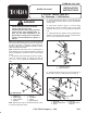
1. Using holes and positioning as shown in figure 1,
mount (2) stiffener angles to stiffener bar with (4)
1/2-13 x 1-1/2" lg. capscrews, flatwashers and lock
nuts.
Figure 1
1. Stiffener bar
2. Stiffener angle
3. Lower frame bar
4. Hitch pin
1
5
6
Left Side Shown
8
4
7
5. Hex nut
6. Lockwasher
7. Jam nut
8. Upper frame bar
2
3
Note: Stiffener bar may be rotated downward (180)
to fit other Implements (PTO).
2. Using holes shown in figure 1, mount (2) hitch pins
to each lower frame bar with hex nuts, lockwashers
and jam nuts.
3. Using holes shown in figure 1, mount a upper
frame bar and each end stiffener bar to each lower
frame bar with (2) 1/2-13 x 2" lg. capscrews and lock
nuts.
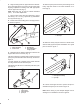
4. Using hole shown in figure 2, mount a frame bar as
sembly to right and left front corners of blower with a
7/8-9 x 2" lg. capscrew and locknut.
Figure 2
1. Frame bar assembly
2. Corner of blower
1
2
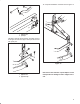
5. Using hole shown in figure 3, secure upper link to
blower with a clevis pin and (2) lynch pins (Fig. 3).
Figure 3
1. Upper link
2. Blower mounting hole
3. Blower
5
1
3
4
4. Clevis pin
5. Upper frame bars &
stiffeners
2