
Installation Instructions


1
All Rights Reserved
Printed in the USA
2004 by The Toro Company
8111 Lyndale Avenue South
Bloomington, MN 55420-1196
H.D. Power Holster Hitch Kit
Workman Vehicles
Model No. 44209–90001 and Up
Form No. 3352–628
Installation Instructions
Installation
Note: Use the instructions on pages 1 thru 3, when
installing the kit on a vehicle with a serial number greater
than 240000001.
1. Position vehicle on a level surface, stop engine,
engage parking brake and remove key from ignition
switch.
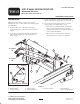
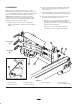
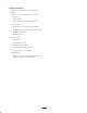
2. Secure each side of holster assembly to hitch frame
with a holster mounting pin and (2) lynch pins, as
shown in figure 1.
3. Secure each hydraulic cylinder to hitch frame with a
cylinder mounting pin and pin hair pin cotter (Fig. 1).
4. Secure lift arm locking pins in storage or locking
position with (2) lynch pins (Fig. 1, inset).
• When pins are in locked position, they hold lift
arms in a locked position in holster assembly
allowing down pressure to be applied to mounting
arms of related attachments..
• When pins are in storage position, they allow
attachment arms to freely float in the holster.
2
3
4
1
To Coupler
“A”
To Coupler
“B”
2
End View of Holster Assembly
6
5
Storage
Position
Locking
Position
Figure 1
1. Holster assembly
2. Holster mounting pin
3. Hydraulic cylinder
4. Cylinder mounting pin
5. Lift arm mounting pin 6. Lift arm locking pin
(shown in storage position)