
Installation Instructions


2004 by The Toro Company
8111 Lyndale Avenue South
Bloomington, MN 55420-1196
Contact us at www.Toro.com
All Rights Reserved
Printed in the USA
Original Instructions (EN)
H.D. Draw Bar Kit
Workman
Vehicles
Model No. 44212
Form No. 3351–426
Installation Instructions
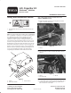
Safety and Instruction Decals
93-8071
1. Hot surface/burn hazard—stay a safe distance from the hot
surface.
Note: On vehicles with serial numbers prior to 239999999,
it is very difficult to install the rear fender mounting screw
once the H.D. Draw Bar has been installed. On units
equipped with fenders, it is recommended that the
capscrews, washers and nuts securing the fender to the
front fender bracket (both sides) and the front two screws
and nuts securing the fender to the vehicle frame channel
(both sides) be removed to allow the fender to flex out for
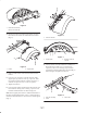
installation of the hitch arm bracket capscrews (Fig. 1). If
fenders are to be installed on vehicle, it is recommended
that the fenders be partially installed by installing the rear
screw and nut holding the fender to the frame before
completing the installation of the H.D. Draw Bar Kit.
1
2
3
Figure 1
1. Fender
2. Front fender bracket
3. Frame channel
Steps 1 thru 8 only pertain to vehicles with serial
numbers 240000001 and up.
1. Remove the bolt and clamp securing the hoses to the
right. rear frame rail (Fig. 2).
1
Figure 2
1. Clamp
2. Secure the hoses to the rear frame tube with a wire tie
(Fig. 3).
1
3
2
Figure 3
1. Hoses
2. Rear frame tube
3. Wire tie
3. In each frame rail, locate the (2) holes that will be used
to mount the hitch arm brackets (Fig. 4). Mark these
hole locations on each fender