
Installation Instructions


2
1
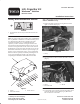
Figure 4
1. Hitch bracket mounting
holes (2 ea. frame rail)
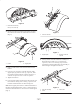
4. Remove the fasteners and the support plates securing
the fenders to the frame rails and remove the fenders
(Fig. 5).
1
2
Figure 5
1. Fender 2. Support plate
5. Drill 1 inch dia. holes at the locations marked on the
fenders.
6. Loosely secure a fender to each side of frame with a
support plate, (5) 3/8–16 x 1.25” lg. capscrews, .406”
I.D. washers and (4) locknuts as shown in figure 5. A
weld nut is in place to secure each rear capscrew.
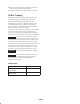
7. Tighten all fasteners.
8. Loosely mount a hitch arm bracket to the inside of each
frame channel with (2) 3/8 x 1 inch lg. capscrews and
locknuts. Position brackets as shown in Figure 6.
Note: If the support plate interferes with the installation of
the hitch arm mounting bracket, remove a small amount of
material from the bracket so it clears the rear mounting bolt
(Fig. 7).
1
Figure 6
1. Hitch arm bracket
2
1
Figure 7
1. Support plate 2. Remove materil as
required
9. Loosely mount each end of draw bar assembly to a
hitch arm bracket with a 1/2 x 1-1/2 inch large
capscrew, a 3/8 x 1-1/2 inch large capscrew and
appropriate locknuts. Position draw bar assembly as
shown in Figure 8. Tighten all fasteners.
1
2
3
Figure 8
1. Draw bar assembly
2. U-bolt
3. Frame tube