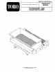
FOREWORD Thank you for buying a high quality Toto turf care product. To get the best performance from this machine, operate and maintain it according to the instructions in this manual. Taro also wants to stress the importance of safety. You and anyone else using or maintaining this machine are strongly urged lo read this manual, especially ali ihe safety instructions. DANGER, WARNING and CAUTION, used with the triangular safety alert symbol, highlight safety messages.
TABLE OF CONTENTS Page Page 3-4 Brush To Conveyor Belt Adjustment .. 16 SAFETY AND INSTRUCTION § Chain Tension .. 18 SPECIFICATIONS 5 Rotation 17 SET UP INSTRUCTIONS . 6-11 Conveyor Belt Installation/Tension . .17 BEFORE OPERATING . .12 Conventionalizing. 17 el 12 Conveyor Belt/Pulley Alignment . 18 OPERATING INSTRUCTIONS . 12-13 HYDRAULIC SCHEMATIC .19 LUBRICATION. 14 STORAGE greenery .2 MAINTENANCE IDENTIFICATION! ORDERING 20 Working On Engine Or Hydraulics THE TOR PROMISE Back Cover Hydraulics ..
SAFETY INSTRUCTIONS (Continued) 11. Using the machine demands attention. Failure to operate vehicle safely may result in an accident, tip aver ot vehicle and serious injury or death. Drive carefully. To prevent tipping or doss of control: A. Use extreme caution, reduce speed and maintain a safe distance around sand traps, ditches, creeks, ramps, any unfamiliar areas or other hazards. B. Watch for holes or other hidden hazards. C. Use caution when aerating vehicle on a steep stop.
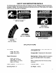
SAFETY AND INSTRUCTION DECALS The following safety and instruction decals are installed on the unit. Replace any decals that becomes damaged or illegible. Part numbers for decals are listed below and in your Pasts Catalog. Order replacements from your Authorized Toto Distributor. CONVEYOR BELT WHILE UNIT 1S SUNNING, Lra BOTH SIDES HOPPER BACK (Part No. 92-4368) ON GUARDS NEAR BEARINGS (Part No, 01-506-0550) LINED UP WITH GATE CONTROL {Part No.
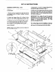
SET UP INSTRUCTIONS NOTE: The Remote Hydraulic Contort Kit (Mode! 07415) must be installed on the Workman before installation of the Topdressing 1800. ATTACHING TOP DRESSER BASE TO WORKMAN (Fig. Attach both Bracket Attachment Mounts (922667) to both sides of the Workman as shown in Fig. 1. Attach with bolts and nuts already in the frame but do not tighten. NOTE: if Workman has a H.D. Hitch Frame installed, the Bracket Attachment Mounts will already be attached.
SE Spacer Mount— ATTACHING TOP DRESSER BASE TO WORKMAN (Continued) 7. Clean dirt from quick couplets before connecting. Dirty couplets can introduce contamination o the system. After cleaning, attach both quick couplets on the top dresser to the Workman. The hoses are marked "A” and "B", match them tc the quick couplets when installing. IMPORTANT: Check hydraulic oil level after installation of Top dresser 1800. Check aeration of top dresser, then recheck hydraulic oil level.
SET UP INSTRUCTIONS TROUBLESHOOTING A. Difficulty in connecting or disconnecting quick couplets: Pressure not relieved (Quick couplet under pressure). Engine running. Remote hydraulic valve not placed in fiat. B. Power Steering Hard: Remote hydraulic valve linkage out of adjustment. Hydraulic oil level low. Hydraulic oif hot. C. Hydraulic leaks: Fittings loose. Fitting missing o-ring. D. Attachment does not function: Quick couplets not fully engaged. Quick couplets are interchanged.
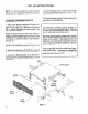
SET UP INSTRUCTIONS ASSEMBLE HOPPER (Fig. 2 & 3) NOTE: Do not secure bolts until all ot the hopper is assembled. 1. Remove all four Guards from each side of the unit. (Part numbers 92-4356, 92-4360, 92-4357 and 92-4361.) 2. Attach the Hopper Brace (F) to Base Frame using (4) 1/4" x 5/8" carriage bolts and whiz nuts. 3. Attach the rear (D) to the Hopper Brace using 1/4" % bolts and whiz nuts. Assemble the sides (G), side Rubber Skirts (H) and Hopper Corner Strips (E) to the Rear (D). Do not secure hardware.
SET UP INSTRUCTIONS ASSEMBLE HOPPER (Continued) — —— Hopper 6. Secure the LH and RH meta skirts (N} to the hopper and side Gate frame with 174" x 5/8" carriage bolts. 9\ Secure tightly. LH Malta Skirt (N) NOTE: Only the LH metal skirt is shown in Fig. 2 and Fig. 3. 7. Attach the Hopper Brace (M) under the front channel of the Hopper Front as shown in Fig. 2. Secure center holes with 1/4" x 5/8" carriage bolts, 8. Attach {4) Corner Brackets (J) to the corners of the hopper including the front Hopper Brace .
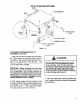
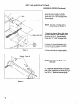
SET UP INSTRUCTIONS INSTALL OPTIONAL LIFT ASSEMBLY (Fig. 5) The Lift Assembly Kit (92-4452) is used to remove or install the Top dresser 1800 from the Workman. 1. Place the Bracket Lift Amendment (92-4448) on 1op of the hopper. 2. Attach the chains as shown in Fig. 5. IMPORTANT: When removing the top dresser, using the Lift Assembly, ALWAYS remove the front attaching bolts and pins before lifting. Lift Chain Top dresser ‘\ T &€ Base Figure 5 A WARNING WHILE USING THE OPTIONAL LIFT ASSEMBLY; DO NOT position
BEFORE OPERATING CHECK HYDRAULIC SYSTEM 1. Visually inspect the hydraulic system for leaks, loose fasteners, missing parts, improperly routed lines. Make all repairs before operating. 2. Assure both quick couplets are full engaged. CONTROLS GATE CONTROL (Fig. 6} The black knob on the left side of the unit, near the brush, is urged to lock the gate into the desired open height position. 1. Loosen the back knob enough to allow it to pivot freely in the slot. 2.
OPERATING INSTRUCTIONS IMPORTANT NOTE: When any other attachments, such as the HD Hitch frame, are installed on the Workman while using the 1800 Top dresser, the weight of those attachments must be subtracted from the payload capacity of the hopper. A method lor determining the total weight of your attachments would be to place the rear tires on a scale. The maximum weight capacity of the rear axis of the Workman is 2600 pounds. 7. Transport to the area to be top dressed. 8.
LUBRICATION BEARINGS (Fig. 7} DRIVE CHAIN (Fig. 7) The top dresser has § serif sealing bearings that Always maintain a light coat of grease on the drive must be [lubricated with a No. 2 Lithium based chain. grease. IMPORTANT: Lubricate the bearings to maintain a slight leakage on the seals. Too much grease can cause overheating.
MAINTENANCE WORKMAN ENGINE OR HYDRAULICS (Fig. 8) IMPORTANT: Always unlock the Dump Stop lever before attempting to attach the cylinder for tilting. 1. The cylinders can be connected to the side of the top dresser te allow tilting of the top dresser for servicing the engine of the Workman. 2. Attach the cylinders as shown in Fig. 8. Use the tilt of the cylinders only for service of the engines or hydraulics underneath. B [Y \ Cylinder Figure 8 IMPORTANT: DO NOT rely on the cylinders to hood up the top dress
MAINTENANCE BRUSH TO CONVEYOR BELT ADJUSTMENT (Fig. 9) The brush is moved back and forth on its mounting slots to adjust it to the conveyor belt. The brush should be as close to the belt as possible without touching. A piece of paper can be inserted between the conveyor belt and the brush to check the adjustment. The brush must be the same height from end to end. The brush adjustment should be checked weekly for wear.
MAINTENANCE ROTATION (Fig. 11) The rotation of the conveyor, brush and the wheels is shown in Fig. 11. If the rotation in not correct, the hydraulic lines are installed incorrectly. See the Hydraulic Schematic. Rotation Direction Figure 11 CONVEYOR BELT INSTALLATION/TENSION (Fig. install a new conveyor belt tallow the instructions below. 1. Turn the top dresser on until the conveyor belt swamis at the edge of the rear roller near the brush. 2.
MAINTENANCE CONVEYOR BELT and PULLEY ALIGNMENT (Fig. 14) 1. Loosen the bearing bolts on each end of the Idler Roller. Loosen the Adjustment bolt to relieve the tension of the conveyor belt. 2. Remove the lacing pin from the conveyor belt on the Top dresser and remove the conveyor belt. 3. Loosen the set screws on all four pulleys. 4. Realign the pulleys using a long straight edge. Line the straight edge up in center of the holes on the frame (See Fig.14).
SEASONAL STORAGE 1. Thoroughly clean the top dresser, especially inside the hopper. The hopper and conveyor bet area should be free of any remaining sand particles. 2. Tighten all fasteners. 3. Lubricate all grease fittings and bearings. Wipe off excess lubricant. 4. The unit should be stored out of the unto .~ prolong the life of the conveyor belt. If stored outside iris recommended to cover the hopper with apart. 5. Check the tension of the drive chain.
The Toto Promise A ONE YEAR LIMITED WARRANTY The Toto Company promises to repair your TOR Product if defective in materials or workmanship. The following time periods from the date of purchase apply: The costs of parts and labor are included, but the customer pays the transportation costs on walk rotary mowers with cutting widths of less than 25", 1. Contact your Authorized TOR Distributor or Commercial Dealer (the Yellow Pages of your telephone directory is a good reference source). ~» .