Form No. 3370-103 Rev A TopDresser 1800 for Workman Heavy-Duty Utility Vehicle Model No. 44225—Serial No. 310000001 and Up To register your product or download an Operator's Manual or Parts Catalog at no charge, go to www.Toro.com.
This product complies with all relevant European directives, for details please see the separate product specific Declaration of Conformity (DOC) sheet. Figure 2 1. Safety alert symbol Introduction This TopDresser is mounted to a Workman Utility Vehicle and is intended to be used by professional, hired operators in commercial applications. It is primarily designed for metering and dispersing materials, under a range of moisture conditions, without clogging or drastically affecting the dispersion.
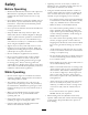
Safety • Lightning can cause severe injury or death. If lightning is seen or thunder is heard in the area, do not operate the machine; seek shelter. Before Operating • Using the machine demands attention. Failure to operate vehicle safely may result in an accident, tip over of vehicle and serious injury or death. Drive carefully. To prevent tipping or loss of control: • Read and understand the contents of this Operator’s Manual before operating the machine.
Maintenance • Before servicing or making adjustments to the TopDresser, stop engine of Workman, set parking brake and remove key from engine to prevent accidental starting of the engine. • Perform only those maintenance instructions described in this manual. If major repairs are ever needed or assistance is desired, contact an Authorized TORO Distributor. • To reduce potential fire hazard, keep the engine free of excessive grease, grass, leaves and accumulations of dirt.
Safety and Instructional Decals Safety decals and instructions are easily visible to the operator and are located near any area of potential danger. Replace any decal that is damaged or lost. 93-9092 1. Crushing hazard of hand—keep bystanders a safe distance from the machine. 105-4586 1. Entanglement hazard, belt—stay away from moving parts. Do not operate the machine with the shields or guards removed; keep the shields and guards in place. 93-9084 1. Lift point 94-1235 2. Tie-down point 1.
Setup Loose Parts Use the chart below to verify that all parts have been shipped. Procedure Description 1 2 3 4 5 Use Qty.
1 Removing the 2/3 or Full Bed No Parts Required Procedure Note: If the Workman is equipped with a H.D. Hitch Frame it does not have to be removed from the vehicle but the weight of the hitch frame must be subtracted from the payload capacity of the hopper. Refer to the Operating Instructions. Figure 4 1. Start the engine. Engage the hydraulic lift lever and lower the bed until the cylinders are loose in the slots. Release the lift lever and turn off the engine. 1. Left rear corner of bed 2.
2. Loosely secure a attachment bracket to each engine frame mounting bracket and vehicle frame with (2) flange head capscrews and flange locknuts previously removed (Figure 5). 2 Mounting the Topdresser Note: If the Workman is equipped with a H.D. Hitch Frame, install spacer mounts, steps 3 & 4, otherwise proceed to step 5. 3. Remove the capscrew, (2) flatwashers and locknut securing each attachment bracket to hitch frame tabs (Figure 6).
Note: If using the optional Lift Assembly Kit (92-4452) to lift the TopDresser, proceed as follows: • Place the lift bracket on top of hopper. • Attach the chains to lift eyes on each corner of hopper. Important: When removing the TopDresser, ALWAYS remove the mounting bolts and pins before lifting. 1 6. Secure each rear mounting bracket to vehicle frame with a clevis pin and (2) lynch pins (Figure 8). 2 G011384 Figure 9 1. TopDresser mounting tab 2. Attachment bracket Figure 8 1.
CAUTION 3 When tilting the hopper of the TopDresser back to perform maintenance on the Workman Connecting the Lift Cylinders • ALWAYS remove the front mounting bolts first. • ALWAYS tilt the TopDresser with an empty load Parts needed for this procedure: 2 Cylinder Pin 2 Capscrew, 1/4 x 3/4 inch 2 Lock Nut, 1/4 inch 4 Using the Safety Support Procedure Parts needed for this procedure: 1. Secure each lift cylinder rod end to TopDresser base with a cylinder pin (Figure 11). 1 2.
1 G011386 Figure 14 1. Hydraulic valve handle 2 Figure 13 1. Bed support 2. Cylinder barrel 3. Bed 1 4. When finished, remove the safety support from the cylinder and insert it into the brackets on the back of the ROPS panel. G011390 Figure 15 1. Hydraulic lift lever CAUTION 2. Hydraulic lift lock 2. On vehicles with serial numbers 240000001 & up, disconnect the two lift cylinder hoses from the hoses secured to the coupler bracket (Figure 16). Insert caps into cylinder hose quick couplers.
Note: Couplers shown in Figure 17 are from vehicles with serial numbers prior to 239999999. Important: Check hydraulic oil level after installation of Topdresser 1800. Check operation of TopDresser, then recheck hydraulic oil level. Operation of vehicle with low oil level can damage pump, remote hydraulics, power steering and vehicle transaxle. Use Dexron III automatic transmission fluid if needed. 4. Start vehicle engine and test rotation of the conveyor and brush.
Product Overview Specifications Controls Note: Specifications and design are subject to change without notice. Gate Metering Control Dimensions and Weights (approx.) The black knobs on the left rear side of the machine are used to adjust and lock the gate into the desired open height position. Length 54 inches Width 73 inches Spreading Width 60 inches 1. Loosen the locking knob (Figure 19) enough to allow it to slide freely in the slot. Inside Clear Width 69 inches Height 49.
Recommended Accessories Operation Jack Stand Assembly (Qty. 4) Requires: Hitch Pin (Qty. 4) Part No. 105-9482-03 Part No. 100-4523 Tachometer/Speedometer Kit (Mitsubishi, liquid cooled gas Workman) Part No. 87-9950 Tachometer/Speedometer Kit (Mitsubishi, liquid cooled diesel Workman) Part No. 87-9970 Rotating parts can grab or pinch. Stay clear of brush and conveyor belt while unit is running. Tachometer/Speedometer Kit (Air cooled gas Workman 3000–4000) Part No.
axle of the Workman 3000/4000 Series is 2600 pounds and 3025 pounds for the Workman HD Series. hand throttle to maintain constant engine speed while topdressing. WARNING DANGER Tipping or rolling the vehicle on a hill will cause serious injury As a general rule, position the weight of the load evenly from front to rear and evenly from side to side.
more power to operate belt. The life of the belt is reduced by approximately 50% when operated below temperatures of 40 degrees F (5 degrees C). Under no conditions should the TopDresser be operated below temperatures of 20 degrees F (-7 degrees C). 1. Increase belt tension by adjusting spring compression to 4 inches (101 mm). Refer to Adjusting Conveyor Belt. 2. Always run belt, before adding material, to assure moisture has not frozen belt system.
Maintenance Note: Determine the left and right sides of the machine from the normal operating position. Recommended Maintenance Schedule(s) Maintenance Service Interval Maintenance Procedure Every 25 hours • Lubricate grease fittings WARNING Before servicing or making adjustments to the machine, stop engine, set parking brake and remove key from ignition switch. Any load material must be removed from hopper before working under raised TopDresser.
Figure 23 1. Brush motor 3. Slide brush into position on right side. Finger tighten nuts. Figure 24 1. Chain cover assembly 4. Slide brush into position on left side. Finger tighten nuts. 2. Spacer (under cover) 2. Loosen bolts and nuts securing motor and sprocket assembly to the main frame (Figure 25). 5. Insert a piece of stiff paper between the brush and the conveyor belt. The brush must be the same height from side to side. 3.
Figure 28 Figure 26 1. Tension rod 2. Compression spring 1. Hopper seal 3. Jam nut 4. Nut 2. Gate edge Important: The fasteners on the covers of this machine are designed to remain on the cover after removal . Loosen all of the fasteners on each cover a few turns so that the cover is loose but still attached, then go back and loosen them until the cover comes free. This will prevent you from accidentally stripping the bolts free of the retainers. 2. Tighten jam nuts to lock adjustment. 3.
rear of machine as damage may result to brash or hydraulic couplers (Figure 33). Important: Make sure hopper is pivoted beyond center and/or secured to wall or post to prevent it from accidentally falling on work area (Figure 33). Figure 30 1. Drive chain 2. Master link 3. Motor G011388 Figure 33 Note: Motor mounting bolts may have to be loosened to disassemble chain link. 3. Loosen jam nuts and nuts on tension rod to release spring tension (Figure 31). 6.
Trouble Shooting Difficulty in connecting or disconnecting quick couplers • Pressure not relieved (Quick coupler under pressure) • Engine running • Remote hydraulic valve not placed in float. (Only on vehicles with serial numbers prior to 239999999) Power Steering Hard • Remote hydraulic valve linkage out of adjustment. (Only on vehicles with serial numbers prior to 239999999) Figure 35 1. Lifting rod • Hydraulic oil level low 2. Slider bed mounting capscrews • Hydraulic oil hot Hydraulic leaks 8.
Storage 1. Thoroughly clean the TopDresser, especially inside the hopper. The hopper and conveyor belt area should be free of any remaining sand particles. 2. Tighten all fasteners. 3. Lubricate all grease fittings and bearings. Wipe off excess lubricant. 4. The unit should be stored out of the sun to prolong the life of the conveyor belt. When stored outside it is recommended to cover the hopper with a tarp. 5. Check the tension of the drive chain. Adjust the tension, if necessary. 6.
Schematics POR T “B” POR T “A” BRUSH MOTOR CONVEYOR MOTOR 3 3 2.8 IN /REV 29.8 IN /REV M M G011389 Hydraulic Schematic (Rev.
The Toro Total Coverage Guarantee A Limited Warranty Conditions and Products Covered The Toro® Company and its affiliate, Toro Warranty Company, pursuant to an agreement between them, jointly warrant your Toro Commercial product (“Product”) to be free from defects in materials or workmanship for two years or 1500 operational hours*, whichever occurs first. This warranty is applicable to all products with the exception of Aerators (refer to separate warranty statements for these products).