
Operator's Manual


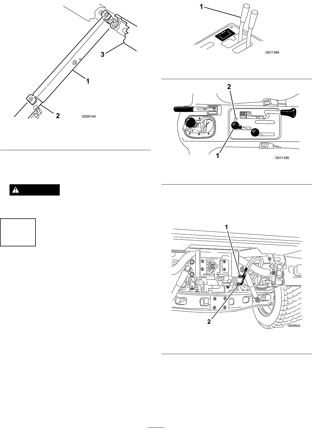
Figure13
1.Bedsupport3.Bed
2.Cylinderbarrel
4.Whennished,removethesafetysupportfromthe
cylinderandinsertitintothebracketsontheback
oftheROPSpanel.
CAUTION
Donottrytolowerbedwithbedsafetysupport
oncylinder.
5
ConnectingtheHydraulic
Couplers
NoPartsRequired
Procedure
1.Onvehicleswithserialnumberspriorto239999999,
movetheremotehydraulicvalvehandle(
Figure14)
totheoatpositionandonvehicleswithserial
numbers240000001&up,movethehydrauliclift
lever(Figure15)backandforthtoremovethe
systempressureandeasethedisconnectionofthe
quickcouplers.
G01 1386
1
Figure14
1.Hydraulicvalvehandle
G01 1390
1
2
Figure15
1.Hydraulicliftlever2.Hydraulicliftlock
2.Onvehicleswithserialnumbers240000001&up,
disconnectthetwoliftcylinderhosesfromthehoses
securedtothecouplerbracket(
Figure16).Insert
capsintocylinderhosequickcouplers.
Figure16
1.QuickcouplerAposition2.QuickcouplerBposition
3.CleananydirtfromTopDresserquickcouplers
(Figure17)beforeconnecting.Dirtycouplers
canintroducecontaminationtothesystem.After
cleaning,attachbothquickcouplerstotheWorkman.
Thehosesaremarked“ A”and“B”,matchthem
tothequickcouplerswheninstalling.Assureboth
quickcouplersarefullengaged.
11