Form No. 3429-174 Rev B Topdresser 1800 Workman® Heavy-Duty Utility Vehicle Model No. 44225—Serial No. 403420001 and Up Register at www.Toro.com.
This product complies with all relevant European directives; for details, please see the separate product specific Declaration of Conformity (DOC) sheet. WARNING CALIFORNIA Proposition 65 Warning Use of this product may cause exposure to chemicals known to the State of California to cause cancer, birth defects, or other reproductive harm. g264615 Figure 1 1.
Contents Safety Safety ....................................................................... 3 General Safety ................................................... 3 Safety and Instructional Decals .......................... 4 Setup ........................................................................ 6 1 Removing the 2/3 or Full Bed ........................... 7 2 Mounting the Topdresser ................................. 7 3 Connecting the Lift Cylinders ...........................
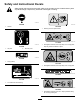
Safety and Instructional Decals Safety decals and instructions are easily visible to the operator and are located near any area of potential danger. Replace any decal that is damaged or missing. decal58-6520 58-6520 decal105-0708 105-0708 1. Grease 1. Warning—thrown object hazard decal117-4979 117-4979 1. Entanglement hazard, belt—keep away from moving parts; keep all guards and shields in place. decal93-9084 93-9084 1. Lift point 2. Tie-down point decal93-9529 93-9529 1.
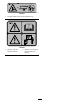
decal138-5941 138-5941 1. Crushing hazard of hand—keep bystanders away. decal138-5949 138-5949 1. Warning—read the Operator's Manual. 2. Warning—receive training before operating the machine.
Setup Loose Parts Use the chart below to verify that all parts have been shipped. Procedure Description 1 2 3 4 5 Use Qty. No parts required – Attachment bracket Clevis pin Lynch pin Cap screw (1/2 x 1 inch) Flat washer Locknut (1/2 inch) Spacer mount Cylinder pin Cap screw (1/4 x 3/4 inch) Locknut (1/4 inch) 2 2 4 4 8 4 2 2 2 2 Bed support (supplied with the Workman vehicle) – Using the bed support. No parts required – Connect the hydraulic couplers. Remove the 2/3 or full bed.
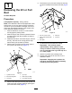
6. 1 Remove the lynch pins and clevis pins securing the pivot brackets to the frame channels (Figure 4). Removing the 2/3 or Full Bed No Parts Required Procedure Lift equipment capacity: 150 kg (330 lb) Note: If the Workman vehicle is equipped with a H.D. Hitch Frame, you do not need to remove it from the vehicle but you must subtract the weight of the hitch frame from the payload capacity of the hopper; refer to the Workman Operator’s manual. 1.
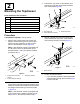
3. 2 Remove the cap screw, 2 flat washers, and locknut securing each attachment bracket to hitch frame tabs (Figure 6). Mounting the Topdresser Parts needed for this procedure: 2 Attachment bracket 2 Clevis pin 4 Lynch pin 4 Cap screw (1/2 x 1 inch) 8 Flat washer 4 Locknut (1/2 inch) 2 Spacer mount g011391 Figure 6 1. Hitch frame tab 2. Frame (Workman vehicle) 3. Attachment frame Procedure 4. Lift equipment capacity: 370 kg (816 lb) 1.
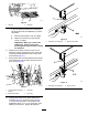
g277068 Figure 8 1. Lift tube 2. Rear flap • If you are using the optional Lift Assembly Kit (92-4452) to lift the topdresser, proceed as follows: A. Place the lift bracket on top of hopper. B. Attach the chains to lift eyes at each corner of hopper. g011384 Figure 10 1. Topdresser mounting tab Important: When you remove the 2. Attachment bracket TopDresser, always remove the mounting bolts and pins before lifting the machine. 6.
Important: 3 On Workman vehicles with serial numbers 240000001 and up, the bed or topdresser cannot be raised unless the lift cylinder hoses are connected to the vehicle. Connecting the Lift Cylinders CAUTION Failure to follow the proper procedures for tilting the hopper of the topdresser could cause serious injury. Parts needed for this procedure: 2 Cylinder pin 2 Cap screw (1/4 x 3/4 inch) 2 Locknut (1/4 inch) • Remove the front mounting bolts before tilting the hopper.
5 Connecting the Hydraulic Couplers No Parts Required Preparing the Machine WARNING Hydraulic fluid escaping under pressure can penetrate skin and cause injury. • Seek immediate medical attention if fluid is injected into skin. Injected fluid must be surgically removed within a few hours by a doctor. g026142 Figure 13 • Ensure that all hydraulic-fluid hoses and lines are in good condition and all hydraulic connections and fittings are tight before applying pressure to the hydraulic system. 1.
Connecting the Hoses 1. Clean any dirt from the topdresser hose quick couplers (Figure 18). g011386 Figure 15 1. Hydraulic valve handle • If your Workman vehicle is serial number 240000001 and up, move the hydraulic lift lever (Figure 16) back and forth. g011403 Figure 18 Quick-Coupler Panel 1. Quick coupler A position 2. g011390 2. Attach the hoses to the quick couplers to the Workman vehicle. Ensure that both quick couplers are full engaged.
Product Overview quick-coupler fittings, connect the hoses to the quick-coupler panel, and repeat steps 2 and 3. Controls Gate Metering Control The black knobs on the left rear side of the machine are used to adjust and lock the gate into the desired open height position. 1. Loosen the locking knob (Figure 20) enough to allow it to slide freely in the slot. 2. Set the gate knob (Figure 20) into the desired position and tighten the locking knob to secure the adjustment. g011387 Figure 19 4.
Specifications Operation Note: Specifications and design are subject to Note: Determine the left and right sides of the machine from the normal operating position. change without notice. Dimensions and Weights Before Operation Length 137 cm (54 inches) Width 185 cm (73 inches) Spreading width 152 cm (60 inches) Before Operation Safety Inside clear width 175 cm (69 inches) • The machine has different balance, weight, Height, mounted on Workman vehicle 126 cm (49.
During Operation During Operation Safety • The owner/operator can prevent and is responsible • • • • • • • for accidents that may cause personal injury or property damage. Wear appropriate clothing, including eye protection; long pants; substantial, slip-resistant footwear; and hearing protection. Tie back long hair and do not wear loose clothing or loose jewelry. Do not operate the machine while ill, tired, or under the influence of alcohol or drugs. Use your full attention while operating the machine.
Operating the Machine • Do not stand behind the machine when unloading. • Unload the topdresser or disconnect it from the vehicle only while on a level surface. • Shut off the attachment when approaching 1. Sit on the seat and engage the parking brake. 2. Disengage the PTO (if so equipped) and move hand throttle lever to OFF position (if so equipped). 3. Place the remote hydraulic-valve handle for the Workman vehicle in the OFF position. 4.
Loading the Hopper DANGER Heavy loads increase stopping distance and reduce your ability to turn quickly without tipping over. 1. Preload Weight Worksheet Transporting or topdressing with a full load can cause shifting of the sand. This shifting happens most often while turning, going up or down hills, suddenly changing speeds or while driving over rough surfaces. Shifting loads can lead to tipovers. Weight of Operator Use caution when transporting or topdressing with a full load.
Sand Application Rate The rate of sand applied depends on the gate setting and the gear/range setting. Sand varies in moisture and coarseness (size of grain) which affects the rate. These factors must be taken into consideration when deciding the amount of sand required for the application. Test a small area to decide the correct amount. To increase the application rate, either open the gate to a higher scale mark or shift the Workman vehicle to a lower gear.
After Operation After Operation Safety • Stop the machine, shut off the engine, remove the key (if equipped), and wait for all movement to stop before you leave the operator’s position, Allow the machine to cool before adjusting, servicing, cleaning, or storing it. • Shut off hydraulic control to the machine whenever you are transporting or not using the it. • Keep all parts of the machine in good working condition and all hardware tightened. • Replace all worn, damaged, or missing decals.
Maintenance Note: Determine the left and right sides of the machine from the normal operating position. Note: Download a free copy of the electrical or hydraulic schematic by visiting www.Toro.com and searching for your machine from the Manuals link on the home page. Maintenance Safety • If possible, do not perform maintenance while the engine is running. Keep away from moving parts. Do not check or adjust the chain tension when the vehicle engine is running.
Belt Maintenance Grease-Fitting Table Location Quantity Roller shaft bearing (Figure 22) 4 Brush shaft bearing (Figure 22) 1 Tensioning the Conveyor-Belt Chain 1. Perform the steps in Preparing for Maintenance (page 20). 2. Remove the chain cover (Figure 23). Important: Lubricate the bearings to maintain a slight leakage between bearings and housings. Too much grease can cause overheating or damage to seals.
4. Adjust forward jam nut to compression spring to 112 mm (4-7/16 inches). 5. Tighten jam rear nut. 6. Repeat steps 3 through 5 at the other side of the machine. 7. Measure the distance between center points of the belt-roller shafts at each side of machine to ensure that the measurements are equal (Figure 26). Equal distance measures approximately 895 mm (35-1/4 inches). g012660 Figure 24 2. Motor and sprocket assembly 1. Conveyer-belt chain 5. Tighten mounting bolts (Figure 24). 6.
Removing the Conveyer Chain 1. Disassembling the Slider Bed Remove chain cover (Figure 28). 1. Loosen forward and rear jam nuts on tension rod to release spring tension (Figure 30). g012667 Figure 30 1. Tension rods 2. Jam nut g012659 Figure 28 2. 1. Chain cover 2. At each side of machine, remove 2 capscrews, 2 washers, and 2 locknuts that secure the hopper to slider-frame rails (Figure 31). Remove master link from chain and remove chain from small sprocket (Figure 29).
Removing the Belt Cut belt and remove it from rollers. Installing the Belt g011388 1. Insert a lift bar though the hole at the left slider-frame rail, and raise the lift bar to tip frame rail slightly; refer to Figure 34 in Disassembling the Slider Bed (page 23). 2. Assemble the belt over the lift bar and rollers as far as possible. 3. Insert a plastic belt tool between each roller and the belt. Figure 32 4.
Installing the Conveyer Chain 1. Assemble the chain onto the small sprocket and secure the chain with the master link (Figure 38). g012670 Figure 36 1. Capscrews (slider-frame rail) 3. Carefully rotate the hopper down onto the slider-frame rails; refer to Figure 32 of Disassembling the Slider Bed (page 23). 4. At each side of machine, secure the hopper to slider-frame rails (Figure 37) with the 2 capscrews, 2 washers, and 2 locknuts that you removed in Disassembling the Slider Bed (page 23).
Brush Maintenance Hydraulic System Maintenance Hydraulic System Safety Checking the Brush for Position and Wear • Seek immediate medical attention if fluid is injected Service Interval: Every 40 hours into skin. Injected fluid must be surgically removed within a few hours by a doctor. Brush must make enough contact with conveyor belt to disperse top-dressing material but not restrict the rotation of the brush.
Cleaning Washing the Machine Wash the machine as needed using water alone or with a mild detergent. You may use a rag when washing the machine. Important: Do not use brackish or reclaimed water to clean the machine. Important: Do not use power-washing equipment g012658 to wash the machine. Power-washing equipment may damage the electrical system, loosen important decals, or wash away necessary grease at friction points. Avoid excessive use of water near the control panel. Figure 41 1. Brush motor 3.
Storage Storage Safety • Shut off the machine, remove the key (if equipped), and wait for all movement to stop before you leave the operator’s position. Allow the machine to cool before adjusting, servicing, cleaning, or storing it. • Do not store the machine or fuel container where there is an open flame, spark, or pilot light, such as on a water heater or other appliance. Preparing the Machine for Storage 1. Thoroughly clean the machine, especially inside the hopper.
Troubleshooting Problem Connecting and/or disconnecting the quick couplers is difficult. It is hard to steer the vehicle. The hydraulic system is leaking. The attachment does not function. Possible Cause Corrective Action 1. The hydraulic system is pressurized. 1. Depressurize the hydraulic system. 2. The engine is running. 3. The remote hydraulic valve is not placed in the float (only on vehicles with serial numbers prior to 239999999). 2. Shut off the engine. 3.
EEA/UK Privacy Notice Toro’s Use of Your Personal Information The Toro Company (“Toro”) respects your privacy. When you purchase our products, we may collect certain personal information about you, either directly from you or through your local Toro company or dealer.
California Proposition 65 Warning Information What is this warning? You may see a product for sale that has a warning label like the following: WARNING: Cancer and Reproductive Harm—www.p65Warnings.ca.gov. What is Prop 65? Prop 65 applies to any company operating in California, selling products in California, or manufacturing products that may be sold in or brought into California.
The Toro Warranty Two-Year or 1,500 Hours Limited Warranty Conditions and Products Covered Parts The Toro Company and its affiliate, Toro Warranty Company, pursuant to an agreement between them, jointly warrant your Toro Commercial product (“Product”) to be free from defects in materials or workmanship for 2 years or 1,500 operational hours*, whichever occurs first. This warranty is applicable to all products with the exception of Aerators (refer to separate warranty statements for these products).