Form No. 3425-477 Rev A Topdresser 1800 Workman® Heavy-Duty Utility Vehicle Model No. 44225—Serial No. 403200001 and Up Register at www.Toro.com.
This product complies with all relevant European directives, for details please see the separate product specific Declaration of Conformity (DOC) sheet. WARNING CALIFORNIA Proposition 65 Warning Use of this product may cause exposure to chemicals known to the State of California to cause cancer, birth defects, or other reproductive harm. g264615 Figure 1 1.
Contents Safety Safety ....................................................................... 3 General Safety ................................................... 3 Safety and Instructional Decals .......................... 4 Setup ........................................................................ 6 1 Removing the 2/3 or Full Bed ........................... 7 2 Mounting the Topdresser ................................. 7 3 Connecting the Lift Cylinders ...........................
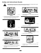
Safety and Instructional Decals Safety decals and instructions are easily visible to the operator and are located near any area of potential danger. Replace any decal that is damaged or missing. decal93-9092 93-9092 1. Crushing hazard of hand—keep bystanders a safe distance from the machine. decal105-4586 105-4586 1. Entanglement hazard, belt—stay away from moving parts. Do not operate the machine with the shields or guards removed; keep the shields and guards in place. decal94-1235 94-1235 1.
decal133-8061 133-8061 5
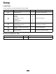
Setup Loose Parts Use the chart below to verify that all parts have been shipped. Procedure Description 1 2 3 4 5 Use Qty. No parts required – Attachment bracket Clevis pin Lynch pin Cap screw (1/2 x 1 inch) Flat washer Locknut (1/2 inch) Spacer mount Cylinder pin Cap screw (1/4 x 3/4 inch) Locknut (1/4 inch) 2 2 4 4 8 4 2 2 2 2 Bed support (supplied with Workman vehicle) – Using the bed support. No parts required – Connect the hydraulic couplers. Remove the 2/3 or full bed.
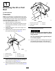
1 Removing the 2/3 or Full Bed No Parts Required Procedure Note: If the Workman is equipped with a H.D. Hitch Frame it does not have to be removed from the vehicle but the weight of the hitch frame must be subtracted from the payload capacity of the hopper. Refer to the Workman Operating Instructions. 1. Park the vehicle on a level surface. 2. Start the engine. Engage the hydraulic lift lever and lower the bed until the cylinders are loose in the slots. 3. Release the lift lever.
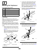
2. 2 Mounting the Topdresser Note: If the Workman is equipped with a H.D. Hitch Frame, install the spacer mounts, steps 3 and 4, otherwise proceed to step 5. Parts needed for this procedure: 2 Attachment bracket 2 Clevis pin 4 Lynch pin 4 Cap screw (1/2 x 1 inch) 8 Flat washer 4 Locknut (1/2 inch) 2 Spacer mount Loosely secure a attachment bracket to each engine frame mounting bracket and vehicle frame with (2) flange-head cap screws and flange locknuts previously removed (Figure 5). 3.
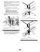
Note: When using a forklift to lift the topdresser, insert the forks through the holes in the rear flap and into the channels. Note: If you are using the optional Lift Assembly Kit (92-4452) to lift the topdresser, proceed as follows: A. Place the lift bracket on top of hopper. B. Attach the chains to lift eyes on each corner of hopper. Important: When removing the TopDresser, always remove the mounting bolts and pins before lifting. 6.
Important: 3 On vehicles with serial numbers 240000001 and up, the bed or topdresser cannot be raised unless the lift cylinder hoses are connected to the vehicle. Connecting the Lift Cylinders CAUTION Failure to follow the proper procedures for tilting the hopper of the topdresser could cause serious injury. Parts needed for this procedure: 2 Cylinder pin 2 Cap screw (1/4 x 3/4 inch) 2 Locknut (1/4 inch) Remove the front mounting bolts before tilting the hopper.
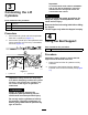
5 Connecting the Hydraulic Couplers No Parts Required Procedure 1. On vehicles with serial numbers prior to 239999999, move the remote hydraulic valve handle (Figure 14) to the float position and on vehicles with serial numbers 240000001 and up, move the hydraulic lift lever (Figure 15) back and forth to remove the system pressure and ease the disconnection of the quick couplers. g026142 Figure 12 1. Bed support 3.
Check for fluid compatibility and take appropriate action if the machine is subsequently used in conjunction with any other product using fluids other than Dexron III ATF. WARNING Hydraulic fluid escaping under pressure can penetrate skin and cause injury. • Seek immediate medical attention if fluid is injected into skin. Injected fluid must be surgically removed within a few hours by a doctor.
Product Overview Important: Ensure that the hoses are routed away from any moving, sharp, or hot components. 5. Controls Visually inspect the hydraulic system for leaks, loose fasteners, missing parts, and improperly routed lines. Make all repairs before operating. Gate Metering Control The black knobs on the left rear side of the machine are used to adjust and lock the gate into the desired open height position. 1. Loosen the locking knob (Figure 19) enough to allow it to slide freely in the slot. 2.
Recommended Accessories Specifications Note: Specifications and design are subject to change without notice. Dimensions and Weights Jack Stand Assembly (Qty. 4) Requires: Hitch Pin (Qty. 4) Part No. 105-9482-03 Part No. 100-4523 Tachometer/Speedometer Kit (Mitsubishi, liquid-cooled gas Workman) Part No. 87-9950 Tachometer/Speedometer Kit (Mitsubishi, liquid-cooled diesel Workman) Part No. 87-9970 Tachometer/Speedometer Kit (air-cooled gas Workman 3000–4000) Part No.
Operation During Operation Note: Determine the left and right sides of the machine from the normal operating position. During Operation Safety • The owner/operator can prevent and is responsible for accidents that may cause personal injury or property damage. Before Operation • Wear appropriate clothing, including eye protection; long pants; substantial, slip-resistant footwear; and hearing protection. Tie back long hair, secure loose clothing, and do not wear loose jewelry.
• Travel with the machine in the lowered position. • Shut off the attachment when approaching – Do not attempt sharp turns or abrupt maneuvers or other unsafe driving actions that may cause a loss of control. people, vehicles, vehicle crossings, or pedestrian crossings. – Be aware of your surroundings when turning or backing up the machine. Ensure that the area is clear and keep all bystanders at a safe distance. Proceed slowly.
3. CAUTION If the safety-interlock switches are disconnected or damaged, the machine could operate unexpectedly, causing personal injury. • Do not tamper with the safety-interlock switches. • Check the operation of the safety-interlock switches daily, and replace any damaged switches before operating the machine. 7. Note: Refer to the attachment Operator’s Manual 8. 4. 5. 6. for procedures on checking the attachment interlock system. Verifying the Clutch-Interlock Switch 1.
9. Sand Precautions Transport to the area to be topdressed. 10. Adjust the metering gate to the desired rate. Lock into position with the black knob. 11. Move the shift lever into LO range position. Select the desired forward speed and begin moving. Refer to Sand Application Rate (page 18). 12. On vehicles with serial numbers prior to 239999999, pull the remote hydraulic lever back to the RUN position.
After Operation After Operation Safety • Park the machine on a firm, level surface. • Always shut off the engine, remove the key (if equipped), wait for all moving parts to stop, and allow the machine to cool before adjusting, servicing, cleaning, or storing the machine. • Ensure that the hopper is in the down position. • Keep all parts of the machine in good working condition and all hardware tightened. • Replace all worn, damaged, or missing decals.
Maintenance Note: Determine the left and right sides of the machine from the normal operating position. Note: Download a free copy of the electrical or hydraulic schematic by visiting www.Toro.com and searching for your machine from the Manuals link on the home page. Recommended Maintenance Schedule(s) Maintenance Service Interval Before each use or daily Every 25 hours Maintenance Procedure • Check the operation of the safety-interlock system. • Check the hydraulic lines and hoses.
Checking the Hydraulic Lines and Hoses Service Interval: Before each use or daily Check the hydraulic lines and hoses for leaks, kinked lines, loose mounting supports, wear, loose fittings, weather deterioration, and chemical deterioration. Make all necessary repairs before operating. Adjusting the Brush g011408 Figure 23 The brush must make enough contact with conveyor belt to disperse the topdressing material but not restrict the rotation of the brush.
1. Loosen the jam nuts and adjust tension rod (Figure 26) nuts to attain the desired tension. g011411 g011409 Figure 26 Figure 24 1. Chain cover assembly 1. Tension rod 2. Compression spring 2. Spacer (under cover) 4. Nut 5. 112 mm (4-7/16 inches) 3. Jam nut 2. 3. Loosen bolts and nuts securing motor and sprocket assembly to the main frame (Figure 25). Rotate motor and sprocket assembly, in mounting slots, until proper tension is achieved. 2. Tighten the jam nuts to lock the adjustment. 3.
g011413 Figure 28 g011414 1. Hopper seal Figure 30 2. Gate edge 1. Drive chain 2. Master link Important: The fasteners on the covers of this machine are designed to remain on the cover after removal. Loosen all of the fasteners on each cover a few turns so that the cover is loose but still attached, then go back and loosen them until the cover comes free. This will prevent you from accidentally stripping the bolts free of the retainers. 1. 3.
5. Pivot the hopper rearward and lean it against a wall, ladder, etc. Do not allow the hopper to rest against the rear of machine, as damage may result to the brush or the hydraulic couplers (Figure 33). Important: Ensure that the hopper is pivoted beyond center and/or secured to a wall or post to prevent it from accidentally falling on the work area (Figure 33). g011418 Figure 35 1. Lift bar 8. g011388 Figure 33 6. Remove the belt as follows: A. Cut the belt and remove it from the rollers. or B.
Storage 1. Thoroughly clean the machine, especially inside the hopper. The hopper and conveyor belt area should be free of any remaining sand particles. 2. Tighten all fasteners. 3. Lubricate all grease fittings and bearings. Wipe off any excess lubricant. 4. The unit should be stored out of the sun to prolong the life of the conveyor belt. When stored outside it is recommended to cover the hopper with a tarp. 5. Check the tension of the drive chain. Adjust the tension, if necessary. 6.
Troubleshooting Problem Connecting and/or disconnecting the quick couplers is difficult. It is hard to steer the vehicle. The hydraulic system is leaking. The attachment does not function. Possible Cause Corrective Action 1. The hydraulic system is pressurized. 1. Depressurize the hydraulic system. 2. The engine is running. 3. The remote hydraulic valve is not placed in the float (only on vehicles with serial numbers prior to 239999999). 2. Shut off the engine. 3.
Notes:
Notes:
Notes:
EEA/UK Privacy Notice Toro’s Use of Your Personal Information The Toro Company (“Toro”) respects your privacy. When you purchase our products, we may collect certain personal information about you, either directly from you or through your local Toro company or dealer.
California Proposition 65 Warning Information What is this warning? You may see a product for sale that has a warning label like the following: WARNING: Cancer and Reproductive Harm—www.p65Warnings.ca.gov. What is Prop 65? Prop 65 applies to any company operating in California, selling products in California, or manufacturing products that may be sold in or brought into California.
The Toro Warranty A Two-Year Limited Warranty Conditions and Products Covered The Toro Company and its affiliate, Toro Warranty Company, pursuant to an agreement between them, jointly warrant your Toro Commercial product (“Product”) to be free from defects in materials or workmanship for two years or 1500 operational hours*, whichever occurs first. This warranty is applicable to all products with the exception of Aerators (refer to separate warranty statements for these products).