Form No. 3350–611 Top Dresser 1800 For Workman 3000/4000 Series Model No.
Write the product model and serial numbers in the space below: Contents Introduction . . . . . . . . . . . . . . . . . . . . . . . . . . . . . . . . . Safety . . . . . . . . . . . . . . . . . . . . . . . . . . . . . . . . . . . . . . Safety and Instruction Decals . . . . . . . . . . . . . . . . . Specifications . . . . . . . . . . . . . . . . . . . . . . . . . . . . . . . . General Specifications . . . . . . . . . . . . . . . . . . . . . Measurements . . . . . . . . . . . . . . . . . . . . . . . . . . . .
• Using the machine demands attention. Failure to operate vehicle safely may result in an accident, tipover of vehicle and serious injury or death. Drive carefully. To prevent tipping or loss of control: Safety Before Operating • Use extreme caution, reduce speed and maintain a safe distance around sand traps, ditches, creeks, ramps, any unfamiliar areas or other hazards. • Read and understand the contents of this Operator’s Manual before operating the machine.
• To reduce potential fire hazard, keep the engine free of excessive grease, grass, leaves and accumulations of dirt. • Before disconnecting or performing any work on the hydraulic system, all pressure in system must be relieved by stopping engine and placing the remote hydraulic valve in the float detent position. • Be sure machine is in safe operating condition by keeping nuts, bolts and screws tight.
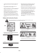
105-0698 93-9092 1. Warning—read the Operator’s Manual. 1. Crushing hazard of hand—keep bystanders a safe distance from the machine. 98-3114 94-1235 1. Entanglement hazard—stay away from moving parts. 1. Maximum load is 635 kg.
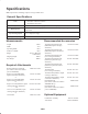
Specifications Note: Specifications and design subject to change without notice. General Specifications Drive Hydraulic driven with Workman remote hydraulics. Belt motor with chain reduction Brush motor direct drive Conveyor Belt Continuous 60” wide traction grip PVC belt with heavy duty monofilament carcass. Metering Gate Spring release flexible edge gate variable from closed to 3″ opening for light to heavy applications. Top Dressing Speed Hopper Capacity Variable to desired application rate.
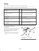
Setup Note: Determine the left and right sides of the machine from the normal operating position. Note: Use this chart as a checklist to ensure that all parts necessary for assembly have been received. Without these parts, total set-up cannot be completed. Some parts may have already been assembled at the factory. Description Qty. Clevis Pin 2 Lynch Pin 4 Attachment Bracket 2 Capscrew – 1/2-13 x 1“ lg.
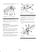
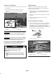
2. Remove clevis pin and (2) lynch pins securing each set of pivot plates to frame channels (Fig. 3). 2 3 1 Figure 4 1. Engine frame mounting bracket 1 2 3 4 Figure 3 1. Vehicle frame channel 2. Pivot plate 2. Vehicle frame 3. Attachment bracket 2. Loosely secure a attachment bracket to each engine frame mounting bracket and vehicle frame with (2) flange head capscrews and flange locknuts previously removed (Fig. 4). 3. Clevis pin 4. Lynch pin Note: If the Workman is equipped with a H.D.
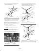
4. Secure a spacer mount to top of each hitch frame tab with the capscrew, (2) flatwashers and locknut previously removed (Fig. 6). 7. Loosely secure top of each attachment bracket (Fig. 8) or spacer mount (Fig. 9) to mounting tab on each side of topdresser with a 1/2–13 x 1” lg. capscrew, (2) flatwashers and locknuts. Tighten all fasteners. 1 1 Figure 6 2 1. Spacer mount 5. Position Topdresser onto vehicle frame, aligning holes in rear mounting brackets with holes in each side of frame (Fig. 7).
Connect Lift Cylinders Safety Support 1. Secure each lift cylinder rod end to topdresser base with a cylinder pin. ALWAYS use the safety supports supplied with the Workman to keep the cylinders in the extended position while performing maintenance. 2. Secure each cylinder pin to topdresser base with a 1/4–20 x 3/4” lg. capscrew, flatwasher and nut (FIg. 10). 1. Push safety support onto cylinder rod, making sure support end tabs rest on end of cylinder barrel and on cylinder rod end. 2.
2. On vehicles with serial numbers 240000001 & up, disconnect the two lift cylinder hoses from the hoses secured to the coupler bracket (Fig. 13). Insert caps into cylinder hose quick couplers. When the remote hydraulic system quick couplers are connected, hydraulic fluid flows from the topdresser to the vehicle. If the hydraulic fluid in the topdresser is not the same or equivalent to vehicle’s, component damage to transaxle or hydraulic system may result.
Safe operation begins before taking the vehicle out for a day’s work. Read and understand the operating instructions in the Toro Workman operator’s manual before using the topdresser. Controls Gate Metering Control Warning The black knobs on the left rear side of the machine are used to adjust and lock the gate into the desired open height position. The interlock switches are for the operator’s protection, so do not bypass them.
Danger Warning As a general rule, position the weight of the load evenly from front to rear and evenly from side to side. Tipping or rolling the vehicle on a hill will cause serious injury If engine stalls or you lose headway on a hill, never attempt to turn vehicle around. Transporting or topdressing with a full load can cause shifting of the sand. This shifting happens most often while turning, going up or down hills, suddenly changing speeds or while driving over rough surfaces.
Cold Weather Operation Maintenance The Topdresser 1800 may be used in cold weather, with certain limitations, to apply a salt/sand mixture on pavement for ice control. The PVC conveyor belt material becomes very stiff in cold weather and requires more power to operate belt. The life of the belt is reduced by approximately 50% when operated below temperatures of 40 F (5 C). Under no conditions should the topdresser be operated below temperatures of 20 F (–7 C).
2. Loosen bolts and nuts securing motor and sprocket assembly to the main frame (Fig, 22). 3. Rotate motor and sprocket assembly, in mounting slots, until proper tension is achieved. 2 1 1 Figure 20 1. Brush motor 3. Slide brush into position on right side. Finger tighten nuts. 4. Slide brush into position on left side. Finger tighten nuts. Figure 22 1. Drive chain 5. Insert a piece of stiff paper between the brush and the conveyor belt. The brush must be the same height from side to side. 2.
3. Check to insure that the center distance between conveyor belt roller shafts (Fig. 24), on each side of machine, are equal distance (approximately 35-1/4″). 1. Remove chain cover, spacer and finger guard (Fig. 26). 35-1/4, 1 1 1 Figure 24 1. Conveyor belt roller shafts 2 Replacing Conveyor Belt Figure 26 When replacing a damaged or worn conveyor belt, always inspect hopper seals (Fig. 25) and gate edge (Fig. 25) for wear or torn edges.
3. Loosen jam nuts and nuts on tension rod to release spring tension (Fig. 28). 1 6. Loosen (2) capscrews, washers and nut, on right side of machine, securing slider bed to frame (Fig. 31). Make sure fasteners are loose enough to allow slider bed to be tipped. 2 1 Figure 28 1. Tension nuts Figure 31 2. Nuts 1. Slider bed mounting capscrews 4. Remove (2) capscrews, washers and nut, on each side of machine, securing hopper to slider bed (Fig. 29). 7.
Trouble Shooting 8. To remove belt: • Cut belt and remove from rollers • Difficulty in connecting or disconnecting quick couplers: or • Pressure not relieved (Quick coupler under pressure). • Insert a plastic belt tool between each roller and belt. Rotate rollers until each tool is positioned to the outside of each roller. Tool must be inserted past rib in center of belt. • Engine running. • Remote hydraulic valve not placed in float.
Hydraulic Schematic PORT B" PORT A" BRUSH MOTOR CONVEYOR MOTOR 3 3 2.8 IN /REV 29.8 IN /REV M M Seasonal Storage 4. Check the tension of the drive chain. Adjust the tension, if necessary. Thoroughly clean the topdresser, especially inside the hopper. The hopper and conveyor belt area should be free of any remaining sand particles. 5. Check the tension of the conveyor belt. Adjust the tension, if necessary. 6.
The Toro General Commercial Products Warranty A Two-Year Limited Warranty Conditions and Products Covered The Toro Company and its affiliate, Toro Warranty Company, pursuant to an agreement between them, jointly warrant your Toro Commercial Product (“Product”) to be free from defects in materials or workmanship for two years or 1500 operational hours*, whichever occurs first.