Form No. 3327–686 Top Dresser 1800 For Workman 3000/4000 Series Model No.
Write the product model and serial numbers in the space below: Contents Introduction . . . . . . . . . . . . . . . . . . . . . . . . . . . . . . . . Safety . . . . . . . . . . . . . . . . . . . . . . . . . . . . . . . . . . . . . Safety and Instruction Decals . . . . . . . . . . . . . . . . Specifications . . . . . . . . . . . . . . . . . . . . . . . . . . . . . . . General Specifications . . . . . . . . . . . . . . . . . . . . . Measurements . . . . . . . . . . . . . . . . . . . . . . . . . . . .
• Using the machine demands attention. Failure to operate vehicle safely may result in an accident, tipover of vehicle and serious injury or death. Drive carefully. To prevent tipping or loss of control: Safety Before Operating • Use extreme caution, reduce speed and maintain a safe distance around sand traps, ditches, creeks, ramps, any unfamiliar areas or other hazards. • Read and understand the contents of this Operator’s Manual before operating the machine.
• To reduce potential fire hazard, keep the engine free of excessive grease, grass, leaves and accumulations of dirt. • Be sure machine is in safe operating condition by keeping nuts, bolts and screws tight. • Make sure all hydraulic line connectors are tight, and all hydraulic hoses and lines are in good condition before applying pressure to the system. • Keep body and hands away from pin hole leaks in hydraulic lines that eject high pressure hydraulic fluid. Use cardboard or paper to find hydraulic leaks.
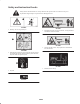
Safety and Instruction Decals Safety decals and instructions are easily visible to the operator and are located near any area of potential danger. Replace any decal that is damaged or lost. 93-9867 99-0015 1. Warning—do not carry passengers. 1. Entanglement hazard, conveyor and brush—keep bystanders a safe distance from the machine. 93-9092 1. Crushing hazard of hand—keep bystanders a safe distance from the machine. 105-4586 1. Entanglement hazard, belt—stay away from moving parts.
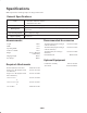
Specifications Note: Specifications and design subject to change without notice. General Specifications Drive Hydraulic driven with Workman remote hydraulics. Belt motor with chain reduction Brush motor direct drive Conveyor Belt Continuous 60” wide traction grip PVC belt with heavy duty monofilament carcass. Metering Gate Spring release flexible edge gate variable from closed to 3″ opening for light to heavy applications. Top Dressing Speed Hopper Capacity Variable to desired application rate.
Setup Note: Determine the left and right sides of the machine from the normal operating position. Note: Use this chart as a checklist to ensure that all parts necessary for assembly have been received. Without these parts, total set-up cannot be completed. Some parts may have already been assembled at the factory. Description Qty. Clevis Pin 2 Lynch Pin 4 Attachment Bracket 2 Capscrew – 1/2-13 x 1“ lg.
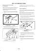
SET-UP INSTRUCTIONS Remove 2/3 Or Full Size Bed (If So Equipped) CAUTION: The full bed weighs approximately 210 pounds, so do not try to remove it by yourself. Get the help of two or three other people. Note: If the Workman is equipped with a H.D. Hitch Frame it does not have to be removed from the vehicle but the weight of the hitch frame must be subtracted from the payload capacity of the hopper. Refer to Operating Instructions, page 11.
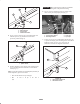
Important When removing the topdresser, ALWAYS remove the mounting bolts and pins before lifting. 1 6. Secure each rear mounting bracket to vehicle frame with a clevis pin and (2) lynch pins (Fig. 7). 2 2 3 3 Figure 5 4 1. Hitch frame tab 2. Vehicle frame 3. Attachment bracket 4 1 Figure 7 4. Secure a spacer mount to top of each hitch frame tab with the capscrew, (2) flatwashers and locknut previously removed (Fig. 6). 1. Vehicle frame channel 2. Mounting brackets 3. Clevis pin 4. Lynch pin 7.
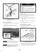
Caution When tilting the hopper of the topdresser back to perform maintenance on the Workman. • ALWAYS remove the front mounting bolts first. • ALWAYS tilt the topdresser with an empty load 1 Safety Support 2 ALWAYS use the safety supports supplied with the Workman to keep the cylinders in the extended position while performing maintenance. 1. Push safety support onto cylinder rod, making sure support end tabs rest on end of cylinder barrel and on cylinder rod end. Figure 9 1.
marked “A” and “B”, match them to the quick couplers when installing. Assure both quick couplers are full engaged. 1. Start vehicle engine and test rotation of the conveyor and brush. Place remote hydraulics lever of Workman in the “run” position. The rotation should be as shown in figure 13. If the rotation is backwards the quick couplers need to be reversed. 1 2 ROTATION DIRECTION Figure 13 Figure 12 1. Coupler “A” 2.
Safe operation begins before taking the vehicle out for a day’s work. Read and understand the operating instructions in the Toro Workman operator’s manual before using the topdresser. Controls Gate Metering Control Warning The black knobs on the left rear side of the machine are used to adjust and lock the gate into the desired open height position. The interlock switches are for the operator’s protection, so do not bypass them.
Danger Warning As a general rule, position the weight of the load evenly from front to rear and evenly from side to side. Tipping or rolling the vehicle on a hill will cause serious injury If engine stalls or you lose headway on a hill, never attempt to turn vehicle around. Transporting or topdressing with a full load can cause shifting of the sand. This shifting happens most often while turning, going up or down hills, suddenly changing speeds or while driving over rough surfaces.
Cold Weather Operation Lubrication The Topdresser 1800 may be used in cold weather, with certain limitations, to apply a salt/sand mixture on pavement for ice control. The PVC conveyor belt material becomes very stiff in cold weather and requires more power to operate belt. The life of the belt is reduced by approximately 50% when operated below temperatures of 40 F (5 C). Under no conditions should the topdresser be operated below temperatures of 20 F (–7 C).
Maintenance Note: Determine the left and right sides of the machine from the normal operating position. Warning Before servicing or making adjustments to the machine, stop engine, set parking brake and remove key from ignition switch. Any load material must be removed from hopper before working under raised topdresser. Always install safety supports on cylinders before working under raised topdresser. 1 Figure 18 1. Brush motor 3. Slide brush into position on right side. Finger tighten nuts. 4.
3. Rotate motor and sprocket assembly, in mounting slots, until proper tension is achieved. 35-1/4, 2 1 1 1 Figure 22 1. Conveyor belt roller shafts Replacing Conveyor Belt When replacing a damaged or worn conveyor belt, always inspect hopper seals (Fig. 23) and gate edge (Fig. 23) for wear or torn edges. Replace worn or torn components to insure proper operation of new conveyor belt. Figure 20 1. Drive chain 2. Motor & sprocket assembly 4. Tighten mounting bolts. 5.
Important Make sure hopper is pivoted beyond center and/or secured to wall or post to prevent it from accidentally falling on work area (Fig. 28). 3 2 1 Figure 25 1. Drive chain 2. Master link 3. Motor Figure 28 6. Loosen (2) capscrews, washers and nut, on right side of machine, securing slider bed to frame (Fig. 29). Make sure fasteners are loose enough to allow slider bed to be tipped. Note: Motor mounting bolts may have to be loosened to disassemble chain link. 3.
Trouble Shooting 8. To remove belt: • Cut belt and remove from rollers • Difficulty in connecting or disconnecting quick couplers: or • Pressure not relieved (Quick coupler under pressure). • Insert a plastic belt tool between each roller and belt. Rotate rollers until each tool is positioned to the outside of each roller. Tool must be inserted past rib in center of belt. • Engine running. • Remote hydraulic valve not placed in float. • Insert a lift bar into hole on left side of machine.
Hydraulic Schematic PORT B" PORT BRUSH MOTOR A " CONVEYOR MOTOR 3 3 2.8 IN /REV 29.8 IN /REV M M Seasonal Storage 4. Check the tension of the drive chain. Adjust the tension, if necessary. Thoroughly clean the topdresser, especially inside the hopper. The hopper and conveyor belt area should be free of any remaining sand particles. 5. Check the tension of the conveyor belt. Adjust the tension, if necessary. 6.
The Toro General Commercial Products Warranty A Two-Year Limited Warranty Conditions and Products Covered The Toro Company and its affiliate, Toro Warranty Company, pursuant to an agreement between them, jointly warrant your 1996 or newer Toro Commercial Product (“Product”) purchased after January 1, 1997, to be free from defects in materials or workmanship for two years or 1500 operational hours*, whichever occurs first.