Form No. 3351-421 5th Wheel Hitch Kit for Heavy-Duty Workman Vehicles Model No. 44230—Serial No. 200000001 and Up Operator’s Manual Register your product at www.Toro.
Contents Introduction . . . . . . . . . . . . . . . . . . . . . . . . . . . . . . . . Safety . . . . . . . . . . . . . . . . . . . . . . . . . . . . . . . . . . . . . Safe Operating Practices . . . . . . . . . . . . . . . . . . . Safety and Instruction Decals . . . . . . . . . . . . . . . Specifications . . . . . . . . . . . . . . . . . . . . . . . . . . . . Set Up Instructions . . . . . . . . . . . . . . . . . . . . . . . . . . Installing the Electric Brake Controller . . . . . . . .
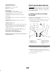
While Operating Safety Using the machine demands attention. Failure to operate vehicle safely may result in an accident, tip over of vehicle, serious injury or death. Drive carefully. To prevent tipping or loss of control: This machine meets or exceeds the B71.1–1998 specifications of the American National Standards Institute, in effect at the time of production. However, improper use or maintenance by the operator or owner can result in injury.
Make sure all hydraulic line connectors are tight and all hydraulic hoses and lines are in good condition before applying pressure to the system. If major repairs are ever needed or assistance i s required, contact an Authorized TORO Distributor. To be sure of optimum performance and safety, always purchase genuine TORO replacement parts and accessories. Replacement parts and accessories made by other manufactures could be dangerous.
Specifications Set Up Instructions Ball Height: 30.7” above ground. Important The Remote Hydraulic Control Kit (Model 07415) must be installed on Workman vehicles with a serial number 239999999 or lower before installation of the 5th Wheel Hitch Kit. Ball Size: 2” Diameter Rated Capacity: 400 lb.(181kg) max. trailer tongue wt. 1500lb.(680kg) max. trailer gross wt. w/o brakes 3500lb.(1587kg) max. trailer GVW w/brakes Construction: Welded Steel hitch plate with rubber isolated ball.
C. Attach black wire with eyelet from the electric controller to the ground bolt near the fuse block. D. Attach 1–terminal red connector to the red wire coming from the fuse block of the Workman. E. Route wire harness alongside main vehicle wire harness toward rear of vehicle. Attach connector end of harness to (92–4524) connector bracket with fasteners. Attach threaded connector cover chain to one of the fasteners. F. Secure wire harness to Workman in several places with wire ties. G. Connect battery.
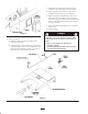
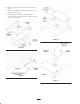
Figure 5 Install Rear Stabilizer Warning 1. Remove tow hitch (if installed) from rear axle of Workman. 2. Install rear stabilizer with four 3/8 x 1 inch bolts, lock washers and hex nuts. Make sure the channel legs are pointing down. Rotating pulleys, fans, and belt in the front 1/3 area of the Workman cargo zone can catch loose clothing or body parts and can cause serious injury.
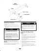
6. Mount operator manual tube to 5th wheel hitch plate. (Fig. 7) 7. Install cover of 5th wheel hitch plate and secure with hardware shown in Fig. 8. 8. Attach the Bracket–Wire (92–4544) with 7/16” x 1–3/4” capscrew, ”SAE” flat washer and lock nut from loose parts bag. (Fig.
Install Male Quick Coupler-Cushman Implements 25”. The Toro ball height is similar to the 31.25” height used on 1991 and prior Cushman 5th wheel kits. Cushman utilizes various adapter kits to change the tongue height to accept either 25” or 31.25” ball heights. It may be necessary to convert your Cushman 5th wheel implement tongue to accept a 31.25” ball height in order to fit and function with the Workman 5th wheel hitch kit.
5. Turn the knob on the tongue socket until it securely grips the ball. Danger 6. If the Workman has a rear 540 PTO kit installed, the PTO shield will have to be rotated downward to assure clearance with the 5th wheel implement tongue. Jack-knifing or sliding could cause loss of control resulting in serious injury or death. • Always insure that the 5th wheel implement brakes are connected and functioning properly before using.
Towing the 5th Wheel Implement 13. To disconnect the 5th wheel implement, reverse the procedures used to connect it. Block the wheels of the 5th wheel implement and insure the jack is securely locked into position before raising the tongue. Relieve hydraulic pressure in hoses prior to disconnecting the quick couplers by lowering 5th wheel implement to ground or against its uplatch device. 1. Read and understand all the operating instructions of the Workman and the 5th wheel implement. 2.
Maintenance 1. Always stop Workman engine and set parking brake before performing any maintenance activity on either the Workman or 5th wheel implement. 2. Lower the 5th wheel implement to the ground or against its uplatch pins to prevent accidental lowering during maintenance. The Workman engine does not need to be running to lower the 5th wheel implement. 3. The engine access cover of the 5th wheel can be removed by unscrewing the two knobs and lifting the cover off the 5th wheel hitch plate.
Hydraulic Schematics Vehicles with serial number 239999999 or lower and w/Optional Remote Hydraulic Kit installed 13
CONTROL STEERING VALVE QUICK CYLINDER COUPLERS DISCONNECT REMOTE LIFT OR CYLINDER ACCESSORY Vehicles with serial number 240000001 or higher 14
Electrical Schematic Ground Brake Controller 15
The Toro General Commercial Products Warranty A Two-Year Limited Warranty Conditions and Products Covered The Toro Company and its affiliate, Toro Warranty Company, pursuant to an agreement between them, jointly warrant your Toro Commercial Product (“Product”) to be free from defects in materials or workmanship for two years or 1500 operational hours*, whichever occurs first.