FOREWORD Thank you for buying a high quality Toto turf care product. To get the best performance from this machine, operate and maintain it according to the instructions in this manual. Toto also wants to stress the importance of safety. You and anyone else using or maintaining this machine are strongly urged to read this manual, especially all the safety instructions, DANGER, WARNING and CAUTION, used with the triangular safety alert symbol, highlight safety messages.
TABLE OF CONTENTS Page Page 3-4 MAINTENANCE SAFETY AND INSTRUCTION DECALS oo 4 Bleeding Hydraulics. ..c..ociiuiuiy " LOOSE PARTS ..ot 5 Changing Filterer. . " SPECIFICATIONS . 6 Oit Tank SET UP INSTRUCTIONS Wheal Motor Nut Torque . . oM installation . it 7 Brush To Conveyor Belt Adjustment 12 Assemble Hopper . Chain Tension BEFORE OPERATING Rotation . Check Hydraulic System. .. 8 Conveyor Belt Installation/Tension . Check Tire Pressure . .
SAFETY INSTRUCTIONS MAINTENANCE 12. NEVER open the hydraulic cap until ALL air pressure has been released. 13. Keep body and hands away from pin hale leaks or nozzles that eject hydraulic fluid under pressure. Use paper of cardboard, not hands to search for leaks. . Hydraulic fluid escaping under pressure can have sufficient force to penetrate skin and do serious damage.
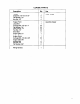
LOOSE PARTS Description Qty Use Tongue Cap screw, x Flat Washer, 172" Hex Nut, 1/2" B = Install tongue Hopper Front Long Skirt Carriage Bolt, x 1° Flat Washer, 1/4" Lock Washer, 1/4° Hex Nut, 1/4" Short Skirt Hopper Side, LH Hopper Back Hopper Brace Carriage Bolt, x 3/4" Hopper Side, RH Support Rod Hex Nut, 3/8° Flat Washer, 3/8" Man N Assemble hopper Wiring Harness
SPECIFICATIONS Dimensions: Height: 40" Length: 88" Width: 83" Hopper Dimensions: Height: Top Width: 76" Bottom Width: 60" Top Length: 40" Bottom Length: 20" Hopper Capacity: 23.5 cubic foot Spreading Width: 60" Top Dressing Speed:. Up to 8 MPH Transporting Speed: Up to 12 MPH Conveyor Belt: Continuous 60" wide composition belt with heavy duty polyester cord. Metering Gate: Infinitely variable from closed to opening for light to heavy applications.
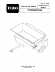
INSTALL TONGUE (Fig, 1) 1. Mount the tongue using (2} 1/2" x bolts, flat washers and nuts provided. Double nut both bolts. ASSEMBLE HOPPER (Fig. 2) 1. Assemble the sides, front, and back (stem A, B, and C) of the hopper and corner guards (totem H) using the 1/4" x 3/4* carriage bolts provided. Attach at all four corners and secure tightly. 2. Set the hopper frame in position on the top dresser. 3. Attach the rear rubber skirt (D) between the frame and the hopper. Use the 1/4" x 1° carriage bolts to mount.
BEFORE OPERATING A4\ DANGER Pressurized Cap Can Cause Serious Injury if Improperly Opened. Never open oil cap without releasing pressure valve stem. Keep face and upper body away from cap while opening. : CHECK HYDRAULIC SYSTEM 1. The hydraulic system is designed to operate on 10W30 8-CC oil. The tank contains 2 gallons of oil. There should be 4" of oil in the tank when full. 2. Pressurize the hydraulic tank with air (20 to 40 Slops.
CONTROLS A4\ DANGER Pressurized Cap Can Cause Serious Injury If improperly Opened. NEVER open oil cap without releasing pressure valve stem. Keep face and upper body away from cap while opening. PRESSURE GAUGE The gauge is a pressure gauge that reads the air pressure in the tank. The recommended air pressure is between 20 40 PSI. OPERATING INSTRUCTIONS A4\ DANGER NEVER carry passengers on the machine or towing vehicle, and keep everyone away from the areas of operation.
LUBRICATION BEARINGS (Fig. 4) ADJUSTMENT LUGS (Fig. 5) The top dresser has & self sealing bearings that Always maintain a light coat of No. 2 Lithium based must be lubricated with a No. 2 Lithium based grease on the threads of the four adjustment lugs. grease. IMPORTANT: Lubricate the bearings to maintain a slight Grieg Lon the seals. Too much grease can cause overheating. DRIVE CHAIN heel: w s Always maintain a light coat of grease on the drive Grease fittings weekly or every 40 operating hours. Chain.
MAINTENANCE BLEEDING HYDRAULIC SYSTEM A\ DANGER Pressurized Cap Can Cause Serious Injury If improperly Opened. Never open oil cap without releasing pressure valve stem. Keep face and upper body away from cap while opening. When any hydraulic parts replaced the system will have to be bled. 1. Push valve stem in to release all pressure from the tank. 2. Remove the air pressure cap. 3. With towing unit, pull the top dresser up to 8 MPH. Pull the top dresser until all “jerking” motion has stopped. 4.
MAINTENANCE E‘RUS)H TO CONVEYOR BELT ADJUSTMENT 9.7 The brush is moved back and forth on its mounting slots to adjust it to the conveyor belt. The brush should be as close to the belt as possible without touching. A piece of paper can be inserted between the conveyor belt and the brush to check the adjustment. The brush must be the same height from end to end. Right Side Left Side Figure 7 1. Loosen the nuts of the bearing on the right hand side. 2.
MAINTENANCE CONVEYOR BELT INSTALLATION/TENSION (Fig. install a new conveyor belt follow the instructions below. 1. Pull the top dresser forward until the conveyor belt seam is in the center of the hopper. 2. Loosen the nuts (A) on the spring rad to release the Figure 11). 3. Remove the lacing (seam wire) from the old conveyor belt. 4. Grab one side of the old conveyor belt and pull it free from the unit. 5. Lay the new belt on the frame and roll it around the rollers bringing the seam to the center. 6.
MAINTENANCE CONVEYOR BELT CARE The conveyor belt rollers may get a coating of topdressing material on them after several uses. If this material is not periodically removed, the roller diameter may become too large or the pulley grooves may get clogged. This may cause damage or failure to the conveyor belt; belt rollers or other top dresser components. Use a water hose, high pressure washer or air pressure to clean the rollers and fish the material out of the unit. 1.
TROUBLE SHOOTING CONDITION CAUSE CORRECTION Conveyor Belt and Brush Not Turning Bad Electrical Connections Blown shames fuse. Hydraulic lines installed backwards Contaminated valve Plug in the wiring harness and make sure wires are making contact. Replace fuse Standing on the left hand side {Chain Guard side) the conveyor belt should rotate clockwise and the brush should rotate counterclockwise. If incorrect, reverse the lines on the corresponding mayors. Remove cartridge to see if blocked.
TROUBLE SHOOTING (Cont.) CONDITION CAUSE CORRECTION Tire(s} Skidding (cont.) * Uneven tire pressure * Check the pressure sifting on the relief valve (1100 PSI) it may be too low. Reset, if necessary. Check tire pressure. All tires should be 20 PSI. Conveyor Belt Not Tracking Properly * Belt pulls to one side Belt Buckles in Center * Bell rides off pulley * Tension is not the same from side to side. Set the spring rad at 4 1/2" on both sides. Run. The belt will pull to the tight side.
SEASONAL STORAGE 1. Thoroughly clean the top dresser, especially inside the hopper. The hopper and conveyor bat area should be free of any remaining sand particles. . 2. Apply a light coat of silicone to the lacing of the conveyor belt. Refer to Maintenance section 3. Inflate all tires to 20 PSl. Or block up the top dresser o remove the weight. 4. Drain and replace hydraulic fluid and filter. inspect all hydraulic lines and fittings. Replace if necessary. Refer to the Maintenance section. 5.
The Toto Commercial Products Two Year Limited Warranty The Toto Company warrants your 1896 or newer Toto Commercial Product (“Product”) purchased after | January 1, 1997, to be free from defects In materials of workmanship for the period of time listed below, Where a warrant able condition exists, Toto will repair the Product at no cost to you including diagnosis, labor, parts, and transportation. This warranty begins on the date the Product is delivered to the original retain purchaser.