Form No.
Revision History Revision Date -- 2007 A 02/2018 Description Initial Issue. Added revision history. © THE TORO COMPANY 2018 This document and all information contained herein is the sole property of The Toro Company (and/or its affiliated companies). No intellectual property rights are granted by the delivery of this document or the disclosure of its content.
Reader Comments The Toro Company Technical Assistance Center maintains a continuous effort to improve the quality and usefulness of its publications. To do this effectively, we encourage user feedback. Please comment on the completeness, accuracy, organization, usability, and readability of this manual by an e-mail to servicemanuals@toro.
NOTES _
Part No. 07154SL (Rev. A) Service Manual Topdresser 1800 and 2500 Preface The purpose of this publication is to provide the service technician with information for troubleshooting, testing and repair of major systems and components on the Topdresser 1800 and 2500. REFER TO THE OPERATOR’S MANUAL FOR OPERATING, MAINTENANCE AND ADJUSTMENT INSTRUCTIONS. Space is provided in Chapter 2 of this book to insert the Operator’s Manual and Parts Catalog for your machine.
This page is intentionally blank.
Chapter 2 – Product Records and Maintenance Product Records . . . . . . . . . . . . . . . . . . . . . . . . . . . Maintenance . . . . . . . . . . . . . . . . . . . . . . . . . . . . . . . Equivalents and Conversions . . . . . . . . . . . . . . . . Torque Specifications . . . . . . . . . . . . . . . . . . . . . . . 2–1 2–1 2–2 2–3 Chapter 3 – Hydraulic System 4–2 4–2 4–3 4–4 4–5 4–8 Chapter 5 – Chassis Specifications . . . . . . . . . . . . . . . . . . . . . . . . . . . . . . 5 – 2 General Information .
This page is intentionally blank.
Safety Table of Contents SAFETY INSTRUCTIONS . . . . . . . . . . . . . . . . . . . . . . Before Operating . . . . . . . . . . . . . . . . . . . . . . . . . . . . While Operating . . . . . . . . . . . . . . . . . . . . . . . . . . . . . Maintenance and Service . . . . . . . . . . . . . . . . . . . . JACKING INSTRUCTIONS (TOPDRESSER 2500) SECURING TOPDRESSER 2500 TO TOW VEHICLE . . . . . . . . . . . . . . . . . . . . . . . . . . . . . . SAFETY AND INSTRUCTION DECALS . . . . . . . . . .
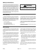
Safety Instructions The Topdresser is designed and tested to offer safe service when operated and maintained properly. Although hazard control and accident prevention partially are dependent upon the design and configuration of the machine, these factors are also dependent upon the awareness, concern and proper training of the personnel involved in the operation, transport, maintenance and storage of the machine. Improper use or maintenance of the machine can result in injury or death.
1. Before servicing or making adjustments, empty hopper and position Topdresser on a level surface. If Topdresser is attached to tow vehicle, engage tow vehicle parking brake, stop engine and remove key from the ignition switch. On Topdresser 2500, chock wheels to prevent it from moving. 2. Make sure machine is in safe operating condition by keeping all nuts, bolts and screws tight. 3.
Jacking Instructions (Topdresser 2500) CAUTION When changing tires or performing other service, use correct hoists or jacks to support the Topdresser. Make sure machine is parked on a solid level surface such as a concrete floor. Always chock or block wheels. Use appropriate jack stands to support the raised machine. If the machine is not properly supported, the machine may move or fall, which may result in personal injury. 1 1 Figure 1 1. Skid 1.
While operating or servicing the Topdresser 2500, make sure that hitch pin is properly positioned in tow vehicle hitch and Topdresser tongue. Hitch pin should be secured with hairpin clip (Fig. 2). Safety Securing Topdresser 2500 to Tow Vehicle 1 2 Figure 2 1. Hitch pin 2. Hairpin clip Safety and Instruction Decals Numerous safety and instruction decals are affixed to the Topdresser. If any decal becomes illegible or damaged, install a new decal.
This page is intentionally blank.
Chapter 2 Product Records and Maintenance PRODUCT RECORDS . . . . . . . . . . . . . . . . . . . . . . . . . MAINTENANCE . . . . . . . . . . . . . . . . . . . . . . . . . . . . . . EQUIVALENTS AND CONVERSIONS . . . . . . . . . . . Decimal and Millimeter Equivalents . . . . . . . . . . . . U.S. to Metric Conversions . . . . . . . . . . . . . . . . . . . TORQUE SPECIFICATIONS . . . . . . . . . . . . . . . . . . . Fastener Identification . . . . . . . . . . . . . . . . . . . . . . .
Equivalents and Conversions 0.
Recommended fastener torque values are listed in the following tables. For critical applications, as determined by Toro, either the recommended torque or a torque that is unique to the application is clearly identified and specified in this Service Manual. These Torque Specifications for the installation and tightening of fasteners shall apply to all fasteners which do not have a specific requirement identified in this Service Manual.
Standard Torque for Dry, Zinc Plated and Steel Fasteners (Inch Series) Thread Size # 6 – 32 UNC Grade 1, 5 & 8 with Thin Height Nuts SAE Grade 1 Bolts, Screws, Studs & Sems with Regular Height Nuts (SAE J995 Grade 2 or Stronger Nuts) in–lb in–lb N–cm 10 + 2 13 + 2 147 + 23 # 6 – 40 UNF # 8 – 32 UNC 13 + 2 25 + 5 282 + 56 # 8 – 36 UNF # 10 – 24 UNC 18 + 2 30 + 5 339 + 56 # 10 – 32 UNF SAE Grade 5 Bolts, Screws, Studs & Sems with Regular Height Nuts (SAE J995 Grade 2 or Stronger Nuts) SAE
Standard Torque for Dry, Zinc Plated and Steel Fasteners (Metric Fasteners) Class 8.8 Bolts, Screws and Studs with Regular Height Nuts (Class 8 or Stronger Nuts) Class 10.9 Bolts, Screws and Studs with Regular Height Nuts (Class 10 or Stronger Nuts) M5 X 0.8 57 + 6 in–lb 644 + 68 N–cm 78 + 8 in–lb 881 + 90 N–cm M6 X 1.0 96 + 10 in–lb 1085 + 113 N–cm 133 + 14 in–lb 1503 + 158 N–cm M8 X 1.25 19 + 2 ft–lb 26 + 3 N–m 28 + 3 ft–lb 38 + 4 N–m M10 X 1.
Other Torque Specifications SAE Grade 8 Steel Set Screws Wheel Bolts and Lug Nuts Recommended Torque Thread Size Thread Size Square Head Hex Socket 1/4 – 20 UNC 140 + 20 in–lb 73 + 12 in–lb 5/16 – 18 UNC 215 + 35 in–lb 145 + 20 in–lb 3/8 – 16 UNC 35 + 10 ft–lb 18 + 3 ft–lb 1/2 – 13 UNC 75 + 15 ft–lb 50 + 10 ft–lb Recommended Torque** 7/16 – 20 UNF Grade 5 65 + 10 ft–lb 88 + 14 N–m 1/2 – 20 UNF Grade 5 80 + 10 ft–lb 108 + 14 N–m M12 X 1.25 Class 8.
Chapter 3 Hydraulic System SPECIFICATIONS . . . . . . . . . . . . . . . . . . . . . . . . . . . . 2 HYDRAULIC SCHEMATICS . . . . . . . . . . . . . . . . . . . . 2 GENERAL INFORMATION . . . . . . . . . . . . . . . . . . . . . 3 Operator’s Manual . . . . . . . . . . . . . . . . . . . . . . . . . . 3 Securing Topdresser to Tow Vehicle . . . . . . . . . . . 3 Relieving Hydraulic System Pressure . . . . . . . . . . 3 Hydraulic Hoses . . . . . . . . . . . . . . . . . . . . . . . . . . . .
Specifications Item Description Brush Motor Displacement (per revolution) Eaton orbital rotor motor, A Series 2.3 Cubic Inches (38 cc) Conveyor Motor Displacement (per revolution) Eaton orbital rotor motor, 2000 Series 29.8 Cubic Inches (488 cc) Wheel Motor (Pump) (Topdresser 2500) Displacement (per revolution) White Hydraulics orbital rotor motor, HB Series 5.
General Information Operator’s Manual The Operator’s Manual provides information regarding the operation, general maintenance and maintenance intervals for your Topdresser machine. Refer to that publication for additional information when servicing the machine. Securing Topdresser 2500 to Tow Vehicle While servicing the Topdresser 2500, make sure that the hitch pin is properly positioned in tow vehicle hitch and Topdresser tongue. The hitch pin should be secured with a hairpin clip (Fig. 1).
Hydraulic Hoses Hydraulic hoses are subject to extreme conditions such as pressure differentials during operation and exposure to weather, sun, chemicals, very warm storage conditions or mishandling during operation and maintenance. These conditions can cause hose damage and deterioration. Some hoses are more susceptible to these conditions than others.
Hydraulic Hose and Tube Installation (O–Ring Face Seal Fitting) C. Use a second wrench to tighten the nut to the correct Flats From Wrench Resistance (F.F.W.R.). The markings on the nut and fitting body will verify that the connection has been properly tightened. 1. Make sure threads and sealing surfaces of the hose/ tube and the fitting are free of burrs, nicks, scratches or any foreign material. 2.
Hydraulic Fitting Installation (SAE Straight Thread O–ring Face Seal Fitting into Component Port) Non–Adjustable Fitting (Fig. 5) 1. Make sure all threads and sealing surfaces of fitting and component port are free of burrs, nicks, scratches or any foreign material. 5. If a torque wrench is not available, or if space at the port prevents use of a torque wrench, an alternate method of assembly is the Flats From Finger Tight (F.F.F.T.) method. 2.
Adjustable Fitting (Fig. 7) 1. Make sure all threads and sealing surfaces of fitting and component port are free of burrs, nicks, scratches or any foreign material. 2. As a preventative measure against leakage, it is recommended that the O–ring be replaced any time the connection is opened. Lock Nut 3. Lightly lubricate the O–ring with clean hydraulic oil. Fitting threads should be clean with no lubricant applied. Back–up Washer 4. Turn back the lock nut as far as possible.
Hydraulic Flow Diagrams WORKMAN REMOTE HYDRAULIC SYSTEM FLOW FROM WORKMAN RETURN TO WORKMAN BRUSH MOTOR 2.3 CU IN/REV CONVEYOR MOTOR 29.
Topdresser 1800 Operation Hydraulic flow for the Topdresser 1800 is provided by the Workman remote hydraulic system. Hydraulic flow (GPM/LPM) and relief pressure, therefore, are determined by the Workman. The brush is driven directly by the hydraulic brush motor. The conveyor belt is driven by the hydraulic conveyor motor with a chain reduction.
WHEEL MOTOR PUMP 5.4 CU IN/REV NOT ENERGIZED SYSTEM RELIEF 1325 PSI CONTROL MANIFOLD BRUSH MOTOR 2.3 CU IN/REV CONVEYOR MOTOR 29.8 CU IN/REV CHARGE MOTOR .813 CU IN/REV CHARGE PUMP .
Topdresser 2500 Operation: Switch Off If the Topdresser is towed in the reverse direction, flow from the wheel motors will reverse. Check valves CV3 and CV1, however, are placed in the hydraulic manifold to prevent reverse flow through the hydraulic system. Hydraulic System While being towed in the forward direction with the Topdresser control handle switch in the OFF position, the wheel motors act as pumps to provide hydraulic flow for the system.
WHEEL MOTOR PUMP 5.4 CU IN/REV ENERGIZED SYSTEM RELIEF 1325 PSI CONTROL MANIFOLD BRUSH MOTOR 2.3 CU IN/REV CONVEYOR MOTOR 29.8 CU IN/REV CHARGE MOTOR .813 CU IN/REV CHARGE PUMP .
Topdresser 2500 Operation: Switch On Hydraulic flow causes rotation of both the brush motor and the conveyor motor which are connected in series. The brush is driven directly by the hydraulic brush motor. The conveyor belt is driven by the hydraulic conveyor motor with a chain reduction. Operating pressure is limited by the system relief valve (R1) located in the control manifold.
Special Tools Order special tools from your Toro Distributor. Hydraulic Pressure Test Kit Part Number: TOR47009 Use to take various pressure readings for diagnostic tests. Quick disconnect fittings provided attach directly to mating fittings on machine test ports without tools. A high pressure hose is provided for remote readings. The Pressure Test Kit contains one each: 1000 PSI (70 Bar), 5000 PSI (350 Bar) and 10000 PSI (700 Bar) gauges. Use gauges as recommended in the Testing Section of this chapter.
Hydraulic Test Fitting Kit Toro Part Number: TOR4079 TORO TEST FITTING KIT (TOR4079) This kit includes a variety of O–ring face seal fittings to enable connection of test gauges to the system. The kit includes: tee’s, unions, reducers, plugs, caps and male test fittings. Figure 11 Hydraulic System O–ring Kit Part Number: 16–3799 The O–ring kit includes O–rings in a variety of sizes for face seal and port seal hydraulic connections.
Troubleshooting The cause of an improperly functioning hydraulic system is best diagnosed with the use of proper testing equipment and a thorough understanding of the complete hydraulic system. A hydraulic system with an excessive increase in heat or noise has a potential for failure. Should either of these conditions be noticed, immediately stop the machine, turn off the tow vehicle engine, locate the cause of the trouble and correct it before allowing the machine to be used again.
ÁÁÁÁÁÁÁÁÁÁÁÁÁÁÁÁÁÁÁÁÁÁÁÁÁÁÁÁÁÁÁÁÁÁÁ ÁÁÁÁÁÁÁÁÁÁÁÁÁ ÁÁÁÁÁÁÁÁÁÁÁÁÁÁÁÁÁÁÁÁÁÁ ÁÁÁÁÁÁÁÁÁÁÁÁÁ ÁÁÁÁÁÁÁÁÁÁÁÁÁÁÁÁÁÁÁÁÁÁ ÁÁÁÁÁÁÁÁÁÁÁÁÁ ÁÁÁÁÁÁÁÁÁÁÁÁÁÁÁÁÁÁÁÁÁÁ ÁÁÁÁÁÁÁÁÁÁÁÁÁ ÁÁÁÁÁÁÁÁÁÁÁÁÁÁÁÁÁÁÁÁÁÁ ÁÁÁÁÁÁÁÁÁÁÁÁÁ ÁÁÁÁÁÁÁÁÁÁÁÁÁÁÁÁÁÁÁÁÁÁ ÁÁÁÁÁÁÁÁÁÁÁÁÁ ÁÁÁÁÁÁÁÁÁÁÁÁÁÁÁÁÁÁÁÁÁÁ ÁÁÁÁÁÁÁÁÁÁÁÁÁ ÁÁÁÁÁÁÁÁÁÁÁÁÁÁÁÁÁÁÁÁÁÁ ÁÁÁÁÁÁÁÁÁÁÁÁÁ ÁÁÁÁÁÁÁÁÁÁÁÁÁÁÁÁÁÁÁÁÁÁ ÁÁÁÁÁÁÁÁÁÁÁÁÁ ÁÁÁÁÁÁÁÁÁÁÁÁÁÁÁÁÁÁÁÁÁÁ ÁÁÁÁÁÁÁÁÁÁÁÁÁ ÁÁÁÁÁÁÁÁÁÁÁÁÁÁÁÁÁÁÁÁÁÁ ÁÁÁÁÁÁÁÁÁÁÁÁÁ ÁÁÁÁÁÁÁÁÁÁÁÁÁÁÁÁÁÁÁÁÁÁ ÁÁÁÁÁÁÁÁÁÁÁÁÁÁÁÁÁÁÁÁÁÁÁÁÁÁÁÁÁÁÁÁÁÁÁ ÁÁÁÁÁÁÁÁÁÁÁÁÁ ÁÁÁÁÁÁÁÁÁÁÁÁÁÁÁÁÁÁÁ
This page is intentionally blank.
Testing The most effective method for isolating problems in the hydraulic system is by using hydraulic test equipment such as pressure gauges in the circuits during various operational checks (see the Special Tools section in this Chapter). 1. Clean machine thoroughly before disconnecting or disassembling any hydraulic component. Always keep in mind the need for cleanliness when working on hydraulic equipment. Contamination can cause excessive wear or binding of hydraulic components.
Charge Pressure Test SCHEMATIC FOR MACHINE WITH SERIAL NUMBER ABOVE 240000000 SHOWN PRESSURE GAUGE WHEEL MOTOR PUMP 5.4 CU IN/REV NOT ENERGIZED SYSTEM RELIEF 1325 PSI CONTROL MANIFOLD BRUSH MOTOR 2.3 CU IN/REV CONVEYOR MOTOR 29.8 CU IN/REV CHARGE MOTOR .813 CU IN/REV CHARGE PUMP .232 CU IN/REV Figure 13 NOTE: The Charge Pressure Test pertains only to Topdresser 2500 machines.
Procedure for Charge Pressure Test: 1. Make sure hydraulic oil is at normal operating temperature by operating the machine for approximately 10 minutes. HYDRAULIC MANIFOLD FROM MACHINE WITH SERIAL NUMBER BELOW 240000000 1 2 2. Park machine on a level surface. Make sure tow vehicle engine is off and that the parking brake is applied. 3. Read and follow Precautions for Hydraulic Testing. IMPORTANT: Make sure to thoroughly clean around all hydraulic connections that will be disassembled. 6.
System Relief Valve (R1) Pressure Test SCHEMATIC FOR MACHINE WITH SERIAL NUMBER ABOVE 240000000 SHOWN WHEEL MOTOR PUMP 5.4 CU IN/REV ENERGIZED SYSTEM RELIEF 1325 PSI CONTROL MANIFOLD BRUSH MOTOR 2.3 CU IN/REV TESTER CONVEYOR MOTOR 29.8 CU IN/REV CHARGE MOTOR .813 CU IN/REV CHARGE PUMP .232 CU IN/REV Figure 16 NOTE: The System Relief Valve (R1) Pressure Test pertains only to Topdresser 2500 machines.
Procedure for System Relief Valve (R1) Pressure Test: 2 1. Make sure hydraulic oil is at normal operating temperature by operating the machine for approximately 10 minutes. 3 2. Park machine on a level surface. Make sure tow vehicle engine is off and that the parking brake is applied. 3. Read and follow Precautions for Hydraulic Testing. Figure 17 IMPORTANT: Make sure to thoroughly clean around all hydraulic connections that will be disassembled. 1. Brush motor 2. Hydraulic hose 4.
System Flow Test SCHEMATIC FOR MACHINE WITH SERIAL NUMBER ABOVE 240000000 SHOWN WHEEL MOTOR PUMP 5.4 CU IN/REV ENERGIZED SYSTEM RELIEF 1325 PSI CONTROL MANIFOLD BRUSH MOTOR 2.3 CU IN/REV TESTER CONVEYOR MOTOR 29.8 CU IN/REV CHARGE MOTOR .813 CU IN/REV CHARGE PUMP .232 CU IN/REV Figure 20 NOTE: The System Flow Test pertains only to Topdresser 2500 machines.
Procedure for System Flow Test: 2 1. Make sure hydraulic oil is at normal operating temperature by operating the machine for approximately 10 minutes. 3 2. Park machine on a level surface. Make sure tow vehicle engine is off and that the parking brake is applied. 3. Read and follow Precautions for Hydraulic Testing. IMPORTANT: Make sure to thoroughly clean around all hydraulic connections that will be disassembled. 1 5. Install hydraulic tester (flow meter) between disconnected hose and fitting.
Brush Motor Efficiency Test SCHEMATIC FOR MACHINE WITH SERIAL NUMBER ABOVE 240000000 SHOWN WHEEL MOTOR PUMP 5.4 CU IN/REV ENERGIZED SYSTEM RELIEF 1325 PSI CONTROL MANIFOLD CONVEYOR MOTOR 29.8 CU IN/REV BRUSH MOTOR 2.3 CU IN/REV PLUG CAP CHARGE MOTOR .813 CU IN/REV CHARGE PUMP .232 CU IN/REV Figure 23 NOTE: The Brush Motor Efficiency Test pertains only to Topdresser 2500 machines.
Rotation speed of the Topdresser brush can be measured with a rotating contact RPM indicator to see if brush motor performance is correct. Before performing this test, the System Flow Test should be completed to make sure that hydraulic flow from the wheel motors is correct. NOTE: If system flow and brush RPM are correct and conveyor is not operating correctly, thoroughly inspect conveyor rollers and bearings for wear or damage.
This page is intentionally blank.
Service and Repairs General Precautions for Removing and Installing Hydraulic System Components Before Repair or Replacement of Components After Repair or Replacement of Components 1. Before removing any parts from the hydraulic system, empty Topdresser hopper and position machine on a level surface. 1. If component failure was severe or if hydraulic system is contaminated, drain entire hydraulic system. Drain and flush all hoses and components. Also, change oil filter. 3.
Brush Motor 6 5 7 3 4 3 8 Loctite #242 5 9 2 1 10 11 12 Antiseize Lubricant 11 54 to 66 ft–lb (74 to 89 N–m) 15 13 14 24 16 17 23 22 21 19 20 RIGHT 19 FRONT 18 Figure 27 1. 2. 3. 4. 5. 6. 7. 8. Hydraulic brush motor Lock nut (2 used) O–ring 45o hydraulic fitting O–ring Hydraulic hose Woodruff key Hydraulic hose Hydraulic System 9. 10. 11. 12. 13. 14. 15. 16.
Removal (Fig. 27) Installation (Fig. 27) 1. Empty Topdresser hopper and position machine on a level surface. Chock wheels to prevent machine from moving. If Topdresser is attached to tow vehicle, engage tow vehicle parking brake, stop engine and remove key from the ignition switch. 1. If removed, install hydraulic fittings with new O–rings into the brush motor ports (see Hydraulic Fitting Installation in the General Information section of this chapter). 3.
Brush Motor Service 9 8 7 6 3 5 4 2 1 16 11 15 14 11 10 11 12 13 Figure 28 1. 2. 3. 4. 5. 6. Cap screw (4 used) Exclusion seal Mounting flange Backup washer Pressure seal Seal 7. 8. 9. 10. 11. Bearing race Thrust bearing Output shaft Housing Seal (3 used) 12. 13. 14. 15. 16.
Hydraulic System This page is intentionally blank.
Conveyor Motor 7 Loctite #242 5 6 4 8 9 3 2 Antiseize Lubricant 1 10 11 23 22 12 54 to 66 ft–lb (74 to 89 N–m) 24 14 13 21 20 19 18 17 15 14 16 RIGHT FRONT Figure 29 1. 2. 3. 4. 5. 6. 7. 8. Flat washer (2 used) Lock washer (2 used) Cap screw (2 used) Roller chain Set screw (2 used) Sprocket Hydraulic brush motor RH motor brace 9. 10. 11. 12. 13. 14. 15. 16.
7. Slide sprocket from conveyor motor shaft. Locate and retrieve square key from motor shaft. Topdresser 2500 5 8. Read the General Precautions for Removing and Installing Hydraulic System Components at the beginning of the Service and Repairs section of this chapter. 8 4 3 1 2 10.Disconnect hydraulic lines from fittings on conveyor motor. Allow hydraulic oil to drain from lines into a suitable container. Put caps or plugs on open hydraulic lines and fittings to prevent contamination.
Conveyor Motor Service 3 8 11 3 10 12 9 7 6 5 2 4 20 21 50 in–lb (6 N–m) 16 22 3 19 1 14 15 17 18 37 ft–lb (50 N–m) 13 3 Figure 32 1. 2. 3. 4. 5. 6. 7. 8. Exclusion seal Bearing housing Seal Back–up ring Shaft seal Shaft and bearing kit Shaft face seal Wear plate 9. 10. 11. 12. 13. 14. 15. Main drive Geroler assembly Valve drive Valve plate Valve Balance ring Outer face seal 16. 17. 18. 19. 20. 21. 22.
Hydraulic System This page is intentionally blank.
Wheel Motor (Topdresser 2500) 8 1 7 6 5 9 10 11 12 Antiseize Lubricant 13 Loctite #242 14 4 15 3 2 16 19 20 18 17 22 21 23 25 24 RIGHT FRONT Figure 33 1. 2. 3. 4. 5. 6. 7. 8. 9. Frame O–ring 45o hydraulic fitting O–ring Hydraulic hose Hydraulic hose O–ring 45o hydraulic fitting (2 used) O–ring Hydraulic System 10. 11. 12. 13. 14. 15. 16. 17.
1. Empty Topdresser hopper and position machine on a level surface. Chock wheels to prevent machine from moving. If Topdresser is attached to tow vehicle, engage tow vehicle parking brake, stop engine and remove key from the ignition switch. 2. Loosen but do not remove two (2) lock nuts (item 11) that secure wheel motor to frame. 3. Remove cap screw (item 16), lock washer (item 17) and flat washer (item 15) from wheel motor shaft. 5.
Wheel Motor Service (Topdresser 2500) 3 5 7 9 1 10 2 11 6 12 4 50 ft–lb (67 N–m) 8 13 3 14 15 17 3 16 15 18 20 22 19 24 26 16 27 21 23 25 Figure 35 1. 2. 3. 4. 5. 6. 7. 8. 9. Screw (4 used) End cover Body seal Piston spring Backup seal O–ring seal Piston Commutator seal Commutator assembly 10. 11. 12. 13. 14. 15. 16. 17. 18. 19. 20. 21. 22. 23. 24. 25. 26. 27.
4. Remove end cover taking care to not drop piston. Using needle nose pliers, lift piston (item 7) from end cover. Remove and discard backup seal (item 5) and O–ring seal (item 6) from piston. MARKER LINE 5. Remove piston spring (item 4) from end cover. IMPORTANT: When removing commutator seal (item 8), be careful not to scratch or damage commutator assembly. MARKER LINE 6. Lift commutator assembly (item 9) from motor. Place commutator on a flat, clean surface with the seal facing up.
5. Install high pressure seal (item 24) into the housing groove. 6. Install the backup shim (item 25) into the housing: A. Slightly squeeze the shim between thumb and forefinger to bow the shim. 0.080” to 0.100” (2.0 to 2.5 mm) B. While maintaining the bow in the shim, start the shim into the housing groove. C. Use a small screwdriver to carefully push the shim fully into the groove. Figure 38 7. Install the wire ring (item 26) into the housing groove making sure that the ring ends are butted. 1 8.
20.Make sure that marker lines (Fig. 36) on installed components are aligned. Also, make sure that bolt holes through components are aligned. If parts need re–alignment, make sure that drive link end still protrudes above the surface of the manifold. 21.With the metal side of the commutator seal (item 8) facing up, use finger pressure to press the commutator seal down into the commutator. The seal should be flush with the commutator surface. 22.
Hydraulic Control Manifold (Topdresser 2500) Serial Number Below 240000000 37 ft–lb (50 N–m) 2 1 3 4 14 5 15 3 7 12 7 6 8 55 ft–lb (74 N–m) 9 4 37 ft–lb (50 N–m) 50 ft–lb (67 N–m) 36 in–lb (4.1 N–m) 12 13 14 16 12 Rear View 11 10 Front View 1 17 18 14 19 55 ft–lb (74 N–m) 27 11 12 20 RIGHT FRONT 24 28 23 21 22 37 ft–lb (50 N–m) 55 ft–lb (74 N–m) 24 26 14 25 12 12 Figure 40 1. 2. 3. 4. 5. 6. 7. 8. 9. 10.
Serial Number Above 240000000 3 2 3 4 11 12 9 11 10 9 6 7 6 1 3 2 8 4 Rear View Front View 37 ft–lb (50 N–m) 50 ft–lb (67 N–m) 36 in–lb (4.1 N–m) 13 Hydraulic System 5 37 ft–lb (50 N–m) 19 22 14 15 7 16 21 5 17 20 RIGHT 4 FRONT 3 2 11 10 9 18 19 37 ft–lb (50 N–m) 37 ft–lb (50 N–m) Figure 41 1. 2. 3. 4. 5. 6. 7. 8. Hydraulic manifold O–ring Hydraulic fitting (5 used) O–ring O–ring Hydraulic fitting (2 used) O–ring 90o hydraulic fitting 9. 10. 11. 12. 13. 14. 15.
2. Relieve sweeper hydraulic system pressure. 1 NOTE: The ports on the control manifold are marked to identify hydraulic connections. Example: R1 is the system relief valve port (See Hydraulic Schematic in Chapter 6 – Foldout Diagrams to identify the function of the hydraulic lines and cartridge valves at each manifold port location). 2 3. Label all control manifold electrical and hydraulic connections for assembly purposes. 4.
IMPORTANT: Use care when handling the valve cartridge. Slight bending or distortion of the stem tube can cause binding and malfunction. 2. Position hydraulic manifold to the frame mounting bracket. Install four (4) cap screws and flat washers to secure manifold to machine. B. Thread cartridge valve carefully into correct manifold port. The valve should go in easily without binding. 3. Make sure all hydraulic connections, ports and fittings are clean. 8.
This page is intentionally blank.
Chapter 4 Electrical System Table of Contents 2 2 3 4 5 5 6 6 7 8 8 Electrical System GENERAL INFORMATION . . . . . . . . . . . . . . . . . . . . . ELECTRICAL DIAGRAMS . . . . . . . . . . . . . . . . . . . . . SPECIAL TOOLS . . . . . . . . . . . . . . . . . . . . . . . . . . . . . TROUBLESHOOTING . . . . . . . . . . . . . . . . . . . . . . . . . COMPONENT TESTING . . . . . . . . . . . . . . . . . . . . . . . Control Handle Switch . . . . . . . . . . . . . . . . . . . . . . . Fuse . . . . . . . . . . . .
1000 1 General Information The Topdresser 1800 uses no electrical components. Information in this chapter pertains only to Topdresser 2500 machines. Electrical power to the Topdresser 2500 is provided by the tow vehicle battery. Three (3) wire harnesses are used on the Topdresser 2500 (Fig. 1). The battery wire harness attaches to the tow vehicle battery. The switch wire harness connects the control handle to the battery wire harness.
Special Tools Multimeter The multimeter can test electrical components and circuits for current (amps), resistance (ohms) or voltage. NOTE: Toro recommends the use of a DIGITAL Volt– Ohm–Amp multimeter when testing electrical circuits. The high impedance (internal resistance) of a digital meter in the voltage mode will make sure that excess current is not allowed through the meter. This excess current can cause damage to circuits not designed to carry it.
Troubleshooting CAUTION Remove all jewelry, especially rings and watches, before doing any electrical troubleshooting or testing. Disconnect the trailer wire harness from the tow vehicle unless the test requires battery voltage. Problem Possible Causes Brush and conveyor do not rotate when control handle switch is turned to the ON position. Problem with power or ground from vehicle. Fuse (5 Amp) is faulty. Trailer, switch and/or battery wire harnesses are not connected or are faulty.
Component Testing For accurate resistance and/or continuity checks, electrically disconnect the component being tested from the circuit (e.g. disconnect the switch connectors before doing a continuity check on switch). CAUTION When testing electrical components for continuity with a multimeter (ohms setting), make sure that power to the circuit has been disconnected.
1000 1 Fuse The Topdresser 2500 uses a single 5 amp fuse for circuit protection. The fuse holder is located in the battery wire harness (Fig. 5). Testing 2 Remove fuse from the fuse holder for testing. Fuse should have continuity between fuse terminals. 3 1 4 Figure 5 1. Battery wire harness 2. Switch wire harness 3. Trailer wire harness 4. Fuse Diode Assembly A diode assembly (Fig. 6) is used in the Topdresser 2500 trailer wire harness (see wire harness drawings in Chapter 6 – Foldout Diagrams).
Solenoid Valve Coil The hydraulic system on the Topdresser 2500 uses a solenoid valve coil on the hydraulic control manifold at port S1 (Fig. 8 and 9). The coil is energized when the control handle switch is in the ON position. HYDRAULIC MANIFOLD FROM MACHINE WITH SERIAL NUMBER BELOW 240000000 1 2 NOTE: If the Topdresser 2500 is equipped with the optional brake kit, a second solenoid valve coil will be included on the hydraulic control manifold at port S2.
Service and Repairs Solenoid Valve Coil The solenoid valve coil (S1) on the Topdresser 2500 hydraulic control manifold (Fig. 10 and 11) can be replaced without opening the hydraulic system. HYDRAULIC MANIFOLD FROM MACHINE WITH SERIAL NUMBER BELOW 240000000 36 in–lb (4.1 N–m) NOTE: If the Topdresser 2500 is equipped with the optional brake kit, a second solenoid valve coil will be included on the hydraulic control manifold at port S2. 1 3 Removal 1.
Chapter 5 Chassis Table of Contents Chassis SPECIFICATIONS . . . . . . . . . . . . . . . . . . . . . . . . . . . . 2 GENERAL INFORMATION . . . . . . . . . . . . . . . . . . . . . 3 Operator’s Manual . . . . . . . . . . . . . . . . . . . . . . . . . . 3 Securing Topdresser 2500 to Tow Vehicle . . . . . . 3 SERVICE AND REPAIRS . . . . . . . . . . . . . . . . . . . . . . 4 Brush Guard . . . . . . . . . . . . . . . . . . . . . . . . . . . . . . . 4 Brush . . . . . . . . . . . . . . . . . . . . . . . . . . .
Specifications Item Description Tires (Topdresser 2500) Size (Before Serial Number 250000000) Size (After Serial Number 250000000) Pressure 18 x 10.5 – 8, 4 Ply, Tubeless 18 x 9.
General Information Operator’s Manual The Operator’s Manual provides information regarding the operation, general maintenance and maintenance intervals for your Topdresser machine. Refer to that publication for additional information when servicing the machine. Securing Topdresser 2500 to Tow Vehicle While operating or servicing the Topdresser 2500, make sure that hitch pin is properly positioned in tow vehicle hitch and sweeper tongue. Hitch pin should be secured with hairpin clip (Fig. 1).
Service and Repairs Brush Guard 20 2 1 3 10 6 7 4 9 3 5 3 10 9 8 3 3 9 10 5 5 19 16 18 9 11 3 17 12 13 14 RIGHT FRONT 15 Figure 2 1. 2. 3. 4. 5. 6. 7. Brush guard Socket head screw Flat washer Flange bushing Slide washer Knob Knob Chassis 8. 9. 10. 11. 12. 13. 14. Nylon washer Lock washer Cap screw Spring pin Slide block plate Spring pin Gate handle Page 5 – 4 15. 16. 17. 18. 19. 20.
Removal (Fig. 2) Installation (Fig. 2) 1. Position Topdresser on a level surface with hopper empty. Chock Topdresser wheels to prevent machine from moving. 1. Lower brush guard to machine frame making sure that gate handle (item 14) is positioned in slide block plate mounted on brush guard. 2. Remove knob (item 6) from gate handle (item 14). 2. On Topdresser 1800 machines, place bumper (not shown) to brush guard. 3. Push spring pin (item 13) from gate handle taking care to not damage handle. 4.
Brush 6 5 7 3 4 3 8 Loctite #242 5 9 10 2 Loctite #242 1 11 12 Antiseize Lubricant 11 54 to 66 ft–lb (74 to 89 N–m) 15 13 14 24 17 23 25 22 16 21 19 20 RIGHT 19 FRONT 18 Loctite #242 Figure 3 1. 2. 3. 4. 5. 6. 7. 8. 9. Hydraulic brush motor Lock nut (2 used) O–ring 45o hydraulic fitting O–ring Hydraulic hose Woodruff key Hydraulic hose Hydraulic fitting 10. 11. 12. 13. 14. 15. 16. 17.
1. Position Topdresser on a level surface with hopper empty. Chock Topdresser wheels to prevent machine from moving. 2. Remove brush guard from machine (see Brush Guard Removal in this section). 3. Loosen two (2) lock nuts that secure hydraulic brush motor to hopper frame. Do not fully remove lock nuts from cap screws. NOTE: Normal brush rotation is counter–clockwise as viewed from left side of Topdresser (Fig. 4). 4. Loosen set screw (item 17) that secures bearing locking collar to brush shaft.
Rollers Loctite #242 Antiseize Lubricant 3 24 4 5 6 2 Antiseize Lubricant 8 7 9 1 Antiseize Lubricant 5 Loctite #242 5 25 23 22 10 11 10 RIGHT FRONT 12 21 13 14 5 20 19 Antiseize Lubricant 18 17 16 15 Figure 5 1. 2. 3. 4. 5. 6. 7. 8. 9. Slider bed frame Driven sprocket Set screw (2 used) Sprocket spacer Bearing Rear roller Conveyor belt Wear plate (2 used) Pop rivet (18 used) 10. 11. 12. 13. 14. 15. 16. 17.
Removal (Fig. 5) Topdresser 2500 1. Position Topdresser on a level surface with hopper empty. Chock Topdresser wheels to prevent machine from moving. 5 6 3 2. Remove conveyor belt from machine (see Operator’s Manual): 4 8 3 2 B. Remove fasteners that secure hopper to frame. Pivot hopper rearward and lean against wall or post (Fig. 8). Do not allow hopper to rest against rear of machine as damage may result to brush or other components.
NOTE: The rear roller has a textured surface and has a key slot for the drive sprocket. NORMAL ROTATION DIRECTION 1 2. Position roller to frame. Secure bearings to frame with four (4) screws and lock washers. 3. Center roller between bearings. Also, make sure that pulley groove in roller aligns with slot in slider bed. NOTE: Normal roller rotation is clockwise as viewed from left side of machine (Fig. 9). 4.
Chassis This page is intentionally blank.
Wheels (Topdresser 2500) 1 70 to 90 ft–lb (95 to 122 N–m) 5 4 3 RIGHT 2 FRONT Figure 10 1. Trailer frame 2. Lug bolt (5 used per wheel) Chassis 3. Wheel assembly (4 used) 4. Cradle assembly (2 used) Page 5 – 12 5.
Wheel Removal (Fig. 10) Wheel Installation (Fig. 10) 1. Position Topdresser on a level surface with hopper empty. Have Topdresser attached to towing vehicle, engage vehicle parking brake, stop engine and remove key from the ignition switch. Chock Topdresser wheels to prevent it from moving. 1. Position wheel to wheel hub on cradle. Make sure that the valve stem is facing out (away from wheel hub). 2. Secure wheel to sweeper with five (5) lug bolts. 3. Lower machine to ground. 2.
Cradle Axle (Topdresser 2500) 17 4 230 to 270 ft–lb (312 to 366 N–m) 15 16 3 6 4 Loctite #242 2 14 12 8 11 230 to 270 ft–lb (312 to 366 N–m) 9 1 10 5 7 5 18 1 Loctite #242 13 6 7 Loctite #242 Figure 11 1. 2. 3. 4. 5. 6. Wheel hub Flat washer (4 used per bearing) Cap screw (4 used per bearing) Lock washer (4 used per bearing) Flange bearing (2 used per cradle) Lock nut 7. 8. 9. 10. 11. 12.
7. Loosen and remove set screw from the locking collar on both flange bearings. 8. Remove four (4) cap screws, lock washers and flat washers that secure flange bearings to cradle. Slide bearing assemblies from cradle and axle. 9. Remove chain from axle sprocket and pull axle assembly from cradle. 10.If necessary, remove sprocket and taper lock bushing from axle: A. Remove three (3) cap screws and lock washers that secure sprocket to bushing. Remove sprocket from bushing. B.
Cradle Assembly (Topdresser 2500) 4 Antiseize Lubricant 3 1 7 5 8 10 6 11 9 23 24 Loctite #242 16 2 15 4 19 3 Loctite #242 20 70 to 90 ft–lb (95 to 122 N–m) 21 14 13 18 17 12 22 Figure 13 1. 2. 3. 4. 5. 6. 7. 8. Frame Flange bearing (2 used per cradle) Flat washer Lock nut Set screw Wheel motor (pump) Square key Sprocket Chassis 9. 10. 11. 12. 13. 14. 15. 16.
Removal (Fig. 13) Installation (Fig. 13) 1. Position Topdresser on a level surface with hopper empty. Have Topdresser attached to towing vehicle, engage vehicle parking brake, stop engine and remove key from the ignition switch. Chock Topdresser wheels to prevent machine from moving. 1. Install all removed components to cradle assembly (see Cradle Axle Installation in this section). 2.
This page is intentionally blank.
Chapter 6 Foldout Diagrams Table of Contents 3 3 4 5 6 6 7 7 8 9 Foldout Diagrams HYDRAULIC SCHEMATICS . . . . . . . . . . . . . . . . . . . . Topdresser 1800 . . . . . . . . . . . . . . . . . . . . . . . . . . . . Topdresser 2500 (Serial Number Below 240000000) . . . . . . . . . . . . . . . . . . . . . . . . . . . . . . Topdresser 2500 (Serial Number Above 240000000) . . . . . . . . . . . . . . . . . . . . . . . . . . . . . . ELECTRICAL SCHEMATIC (TOPDRESSER 2500) Electrical Schematic . . . . . . . . .
This page is intentionally blank.
WORKMAN (TOW VEHICLE) REMOTE HYDRAULIC SYSTEM FLOW FROM WORKMAN RETURN TO WORKMAN BRUSH MOTOR 2.3 CU IN/REV CONVEYOR MOTOR 29.
P1 M1 P2 A1 BRAKE SOLENOID (OPTIONAL) SOLENOID S1 S2 B CV1 WHEEL MOTOR PUMP 5.4 CU IN/REV A2 CHARGE RELIEF (R2) 80 PSI CV3 SYSTEM RELIEF (R1) 1500 PSI CV2 T1 CV4 M2 BRUSH MOTOR 2.3 CU IN/REV CONVEYOR MOTOR 29.8 CU IN/REV M M C1 AF AUTO FILL PORT CHARGE MOTOR .813 CU IN/REV Topdresser 2500 Hydraulic Schematic (Serial Number Below 240000000) Page 6 – 4 10 MICRON FILTER CONTROL MANIFOLD C2 M P CHARGE PUMP .
WHEEL MOTOR PUMP 5.4 CU IN/REV SOLENOID SYSTEM RELIEF 1325 PSI CONTROL MANIFOLD BRUSH MOTOR 2.3 CU IN/REV CONVEYOR MOTOR 29.8 CU IN/REV CHARGE MOTOR .813 CU IN/REV CHARGE PUMP .
HYDRAULIC SOLENOID S1 SWITCH WIRE HARNESS BATTERY WIRE HARNESS BLACK TRAILER WIRE HARNESS ORANGE WHITE DIODE WHITE WHITE RED BLACK Topdresser 2500 Electrical Schematic All ground wires are black.
WHITE WHITE BLACK BLACK PINK Topdresser 2500 Trailer Wire Harness Page 6 – 7
RED ORANGE BLACK WHITE BLACK RED Topdresser 2500 Battery Wire Harness Page 6 – 8 WHITE ORANGE PINK BLACK
SWITCH WIRE HARNESS ON MACHINES WITH SERIAL NUMBERS ABOVE 250000000 EQUIPPED WITH SPADE TERMINALS BLACK BLACK WHITE WHITE PINK Topdresser 2500 Switch Wire Harness Page 6 – 9
This page is intentionally blank.