
Service Manual


Topdresser 1800 & 2500Hydraulic System Page 3 – 34
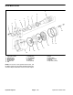
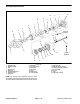
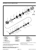
Conveyor Motor
1. Flat washer (2 used)
2. Lock washer (2 used)
3. Cap screw (2 used)
4. Roller chain
5. Set screw (2 used)
6. Sprocket
7. Hydraulic brush motor
8. RH motor brace
9. Brush
10. Hydraulic hose
11. Hydraulic hose
12. LH motor brace
13. 90
o
hydraulic fitting
14. O–ring (2 used)
15. O–ring
16. 90
o
hydraulic fitting
17. O–ring
18. 90
o
hydraulic fitting
19. O–ring
20. O–ring (2 used)
21. Hydraulic conveyor motor
22. Spacer plate
23. Square key
24. Hydraulic fitting
Figure 29
FRONT
RIGHT
5
4
2
1
3
7
8
6
19
18
17
16
15
13
12
14
20
11
10
9
21
22
23
24
54 to 66 ft–lb
(74 to 89 N–m)
Antiseize
Lubricant
14
Loctite #242
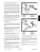
Removal (Fig. 29)
1. Empty Topdresser hopper and position machine on
a level surface. Chock wheels to prevent machine from
moving. If Topdresser is attached to tow vehicle, engage
tow vehicle parking brake, stop engine and remove key
from the ignition switch.
2. Remove brush guard from machine to gain access
to conveyor motor (see Brush Guard Removal in the
Service and Repairs section of Chapter 5 – Chassis).
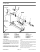
3. Remove chain guard from outside of frame (Figs. 30
and 31).
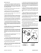
4. Loosen but do not remove two (2) cap screws (item
3), lock washers (item 2) and flat washers (item 1) that
secure conveyor motor to frame.
5. Locate and remove roller chain master link. Position
chain away from conveyor motor sprocket.
6. Loosen two (2) set screws (item 5) that secure
sprocket to conveyor motor shaft.