
Service Manual


Topdresser 1800 & 2500 Hydraulic SystemPage 3 – 35
7. Slide sprocket from conveyor motor shaft. Locate
and retrieve square key from motor shaft.
8. Read the General Precautions for Removing and
Installing Hydraulic System Components at the begin-
ning of the Service and Repairs section of this chapter.
9. Label all hydraulic connections for assembly pur-
poses. Thoroughly clean hydraulic hoses and fittings
prior to loosening hydraulic lines at conveyor motor.
10.Disconnect hydraulic lines from fittings on conveyor
motor. Allow hydraulic oil to drain from lines into a suit-
able container. Put caps or plugs on open hydraulic lines
and fittings to prevent contamination. Remove and dis-
card O–rings.
11.Support conveyor motor to prevent it from shifting.
Remove two (2) cap screws (item 3), lock washers (item
2) and flat washers (item 1) that secure motor to frame.
Remove conveyor motor from the machine. Remove
spacer plate from between motor and frame.
12.If required, remove hydraulic fittings and O–rings
from the conveyor motor. Discard O–rings.
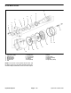
Installation (Fig. 29)
1. If removed, install hydraulic fittings with new O–rings
into the conveyor motor ports (see Hydraulic Fitting
Installation in the General Information section of this
chapter).
2. Position spacer plate and conveyor motor to frame.
Install two (2) cap screws (item 3), lock washers (item 2)
and flat washers (item 1) that secure motor to frame. Do
not fully tighten fasteners at this time.
3. Apply antiseize lubricant to motor shaft. Position
square key into motor shaft slot.
4. Slide sprocket onto motor shaft. Make sure that hub
on sprocket gear goes in toward frame.
5. Position roller chain around conveyor motor sprock-
et and connect roller chain ends with master link.
6. Slide conveyor motor sprocket on shaft to align it with
driven sprocket on conveyor roller. Apply Loctite #242
(or equivalent) to threads of set screws (item 11) and se-
cure sprocket to conveyor motor shaft with two (2) set
screws.
7. Rotate conveyor motor to take slack out of chain, but
not so tight that binding occurs on sprockets. Torque cap
screws from 54 to 66 ft–lb (74 to 89 N–m) to secure
conveyor motor to frame.
8. Check that chain has 0.125” (3.2 mm) deflection at
mid–span between the sprockets. If necessary, reposi-
tion conveyor motor to allow correct chain deflection.
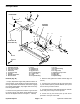
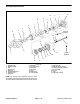
1. Carriage screw
2. Chain guard
3. Flat washer
4. Lock nut
5. Cap screw
6. Lock washer
7. Hyd conveyor motor
8. Drive chain
Figure 30
1
2
4
5
6
7
3
3
Topdresser 2500
8
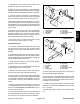
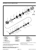
1. Lock nut
2. Flat washer
3. Spacer
4. Guard
5. Chain guard
6. Cap screw
7. Lock washer
8. Cap screw
9. Hyd conveyor motor
10. Drive chain
Figure 31
1
2
4
5
6
7
3
8
2
9
10
Topdresser 1800
9. Remove caps or plugs that were put on any hydraulic
lines and fittings during disassembly.
10.Lubricate new O–rings with clean hydraulic oil and
position on fittings. Using labels made during removal,
correctly connect and secure hydraulic hoses to hydrau-
lic fittings on conveyor motor.
11.Install brush guard to machine (see Brush Guard
Installation in the Service and Repairs section of Chap-
ter 5 – Chassis).
12.Install chain guard to outside of frame (Figs. 30 and
31).
Hydraulic
System