
Service Manual


Topdresser 1800 & 2500Hydraulic System Page 3 – 42
5. Install high pressure seal (item 24) into the housing
groove.
6. Install the backup shim (item 25) into the housing:
A. Slightly squeeze the shim between thumb and
forefinger to bow the shim.
B. While maintaining the bow in the shim, start the
shim into the housing groove.
C. Use a small screwdriver to carefully push the
shim fully into the groove.
7. Install the wire ring (item 26) into the housing groove
making sure that the ring ends are butted.
8. Place the housing in an arbor press with the mount-
ing flange facing down. Press down on the rear housing
bearing until is from 0.164” to 0.205” (4.2 to 5.2 mm) be-
low the housing surface. This allows room for the thrust
washer and thrust bearing to be installed later in the as-
sembly process.
9. Insert shaft up through housing and then press seal
carrier assembly down into housing until the carrier is
against the installed wire ring in the housing.
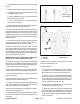
10.Remove shaft from housing and make sure that
there is from 0.080” and 0.100” (2.0 to 2.5 mm) clear-
ance between the rear thrust washer in the housing and
the front bearing (Fig. 38). If not enough clearance ex-
ists, bearing must be repositioned in the housing before
continuing with assembly process.
IMPORTANT: Prevent damage when clamping the
motor in a vise; clamp on the housing only.
11.Mount the housing in a vise with the mounting flange
facing down. Coat shaft with clean hydraulic oil and then
carefully insert shaft down through housing taking care
to not damage the seals in the housing.
12.Place thrust washer (item 16) against the shaft end
and then install thrust bearing (item 15) onto washer.
13.Place a body seal (item 3) into the groove in the rear
face of the housing.
14.Insert the drive link (item 12) into the shaft with the
tapered end of the drive link facing up.
15.Using the marker lines placed before disassembly
(Fig. 36) for orientation, place the wear plate (item 13)
over the drive link and onto the housing.
16.Place a body seal (item 3) into the groove in the face
of the rotor assembly (item 11).
17.Align the splines of the drive link and the rotor assem-
bly and lower the seal side of the rotor assembly to the
wear plate.
Figure 38
0.080” to 0.100”
(2.0 to 2.5 mm)
1. Manifold
2. Drive link
3. Manifold groove
Figure 39
2
1
3
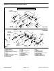
18.Place a body seal (item 3) into the groove in each
face of the manifold (item 10).
19.Install manifold:
A. Lift the drive link approximately 0.100” (2.5 mm)
and place the tip of a small screwdriver under the
disk shaped portion of the drive link to hold it up.
B. With the side of the manifold with the largest
holes down, align the notch in the manifold with the
notch in the rotor. Lower the manifold toward the ro-
tor and engage the disk shaped portion of the drive
link into the manifold groove (Fig. 39).
C. Remove the screwdriver from the drive link and
fully lower the manifold to the rotor.
D. Make sure that the end of the drive link protrudes
above the surface of the manifold. If not, the drive link
disk is not engaged in the manifold groove and the
motor will not operate. Repeat manifold installation
steps if necessary.