
Service Manual

Topdresser 1800 & 2500Page 5 – 14Chassis
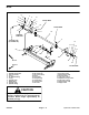
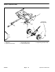
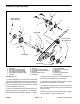
Cradle Axle (Topdresser 2500)
Figure 11
1. Wheel hub
2. Flat washer (4 used per bearing)
3. Cap screw (4 used per bearing)
4. Lock washer (4 used per bearing)
5. Flange bearing (2 used per cradle)
6. Lock nut
7. Set screw
8. Cap screw (3 used per bushing)
9. Lock washer (3 used per bushing)
10. Set screw
11. Cradle assembly (2 used)
12. Cradle axle
13. Taper lock bushing
14. Drive chain with master link
15. Sprocket
16. Wheel motor
17. Lock nut (2 used per motor)
18. Carriage screw
230 to 270 ft–lb
(312 to 366 N–m)
1
2
3
4
5
11
5
1
4
6
7
8
9
10
12
13
14
6
15
16
17
230 to 270 ft–lb
(312 to 366 N–m)
18
7
Loctite #242
Loctite #242
Loctite #242
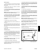
Removal (Fig. 11)
1. Position Topdresser on a level surface with hopper
empty. Have Topdresser attached to towing vehicle, en-
gage vehicle parking brake, stop engine and remove
key from the ignition switch. Chock Topdresser wheels
to prevent machine from moving.
2. Jack or hoist sweeper from ground and support ma-
chine with blocking or jack stands (see Operator’s
Manual and Jacking Instructions in Chapter 1 – Safety).
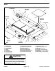
3. Remove both wheels from cradle assembly to be
serviced (see Wheel Removal in this section).
4. Loosen lock nuts that secure wheel motor to cradle.
Rotate motor to obtain slack in drive chain.
5. Rotate axle until master link is located in recessed
area of cradle near wheel motor. Remove master link
from drive chain.
6. Remove lock nuts that secure wheel hubs to cradle
axle. Use puller to remove hubs from axle.