
Operator's Manual


9
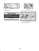
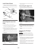
4. At it’s shortest length, the two halves of the PTO shaft
must have at least 1-1/2 inches (37 mm) of additional
clearance to collapse (Fig. 6). If the dimension in step 2
is not at least 1-1/2 inches (37 mm) greater than the
dimension in step 3, the PTO shaft is too long; proceed
to step 5. If there is enough clearance to allow the PTO
shaft to collapse, proceed to step 10.
1-1/2 in.
(37 mm)
1
Figure 6
1. PTO shaft
5. Use the following calculation to establish how much
shorter the shaft must be, when connected, to ensure a
clearance of 1-1/2 inches (37 mm):
A. Subtract the dimension recorded in step 3 from the
dimension recorded in step 2. Record this
dimension.
B. Subtract the result in step 5A from 1-1/2 inches
(37 mm). The PTO shaft must be shortened by this
amount.
6. Using a hacksaw, cut the guards and the steel tubes
shorter by the calculated length. Cut both halves of the
PTO shaft.
7. Deburr the ends of the steel tubes internally and
externally.
8. Remove all debris from the tube sections.
9. Grease the steel tubes liberally.
10. Assemble the PTO shaft and secure it to the blower and
tractor.
11. Measure the shaft. If it is not at least 1-1/2 inches
(37 mm), repeat the procedure.
12. Raise the blower to the highest position. There must be
at least 3 inches (75 mm) of overlap of the halves.
Adjust the 3 point lift stop, if necessary; refer to
Adjusting the 3 Point Lift Stop, page 10.
Connecting the PTO Shaft
1. Connect the PTO shaft to the blower input shaft.
2. Connect the PTO shaft to the rear tractor PTO shaft.
3. Slide the PTO shaft forward as far as it will go.
4. Depress the pin to secure the PTO shaft in place. Slide
the PTO shaft back and forth to make sure it is properly
locked.
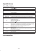
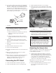
1
2
2
Figure 7
1. PTO shaft 2. Safety chains
5. Connect the shield safety chains from the powershaft
sections to the welded clips on the link arms or to the
PTO shields (Fig. 7). Make sure that the chains remain
slack when the blower is raised or lowered.
If shield chains are not connected, they could
rotate during operation and cause bodily injury.
Keep all PTO shields in place and connect the
shield chains to the link arms or PTO shields.
Caution
Adjusting the Sway Links
Adjust the sway links on the lower draft arms of the 3-point
hitch to minimize side-to-side sway to a maximum of
1 inch (25 mm) on each side.
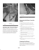
1. Adjust the lower links inboard until they contact the
blower mounting plates (Fig. 8). This will reduce the
stress on the pins. If the tractor has sway chains instead
of sway links, it is recommended that washers be
installed between the lower link arm and lynch pin to
reduce the over hung load on the lift pins.
Note: Refer to the tractor operator’s manual for additional
installation and adjustment procedures.
2. Turn the adjustable link body (if provided) to raise or
lower the link arm until the blower is leveled
side-to-side.