Form No. 3350–449 Debris Blower 600 Model No. 44536—Serial No.
Contents Contents . . . . . . . . . . . . . . . . . . . . . . . . . . . . . . . . . . . . Introduction . . . . . . . . . . . . . . . . . . . . . . . . . . . . . . . . . Safety . . . . . . . . . . . . . . . . . . . . . . . . . . . . . . . . . . . . . . Before Operating . . . . . . . . . . . . . . . . . . . . . . . . . . While Operating . . . . . . . . . . . . . . . . . . . . . . . . . . . Maintenance . . . . . . . . . . . . . . . . . . . . . . . . . . . . . . Safety and Instruction Decals . . . . . . . . . .
Safety – Reduce your speed when making sharp turns and when turning on hillsides. Hazard control and accident prevention are dependent upon the awareness, concern, and proper training of the personnel involved in the operation, transport, maintenance, and storage of the machine. Improper use or maintenance of the machine can result in injury or death. To reduce the potential for injury or death, comply with the following safety instructions. – Avoid sudden starts and stops.
Safety and Instruction Decals Safety decals and instructions are easily visible to the operator and are located near any area of potential danger. Replace any decal that is damaged or lost. 98-3110 1. Danger–See Operator’s Manual 2. Danger–Wear ear protection 3. Thrown object hazard–Keep bystanders away. 4. Always wear eye protection 5. Cutting hazard to hands or feet–wait until all machine components have stopped before touching them. 92–7937 105–0669 1.
105–0707 105–0708 1. Danger–Blown object hazard–Keep bystanders away chute oullet. 105–0627 1. Danger 2. Stop the engine and remove the key from tractor ignition before leaving operator’s position. Disconnect PTO shaft. 3. Read Operator’s Manual before performing any maintenance on machine 105–0709 1. Stay away from moving parts. 2. Do not operate with out belt shield in place. 105–0628 1. Danger 2.
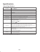
Specifications General Specifications Fan Output 7000 CFM + 200 CFM 165 MPH + 20 MPH Fan Speed 1173 RPM + 20 RPM @ 540 PTO Input Outlet Area 100 square inches Directional Control Caster Wheels Height Adjustment Turf Protection Ground Clearance Fan Fan Housing Drive Mounting: Weight: Deflector chute for 180 degree diversion as standard. Rotational control of gate just behind 3–point hitch Two 13 x 5.00–6 pneumatic rubber tires 0 – 1–1/2 by 1/2 in.
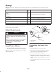
Setup Note: Use this chart as a checklist to ensure that all parts have been received. Without these parts, total setup cannot be completed. Description Qty. Use Castor wheel 2 Axle 2 Washer 8 Cotter pin 4 Drive shaft 1 Mount drive shaft blower and tractor Operator’s Manual 1 Read before operating the machine. Parts Catalog 1 Registration card 1 Mount castor wheels to castor forks Fill out and return to Toro.
Adjusting the PTO Shaft Length 1 Important A long PTO shaft is supplied with the machine to accommodate large variations in the tractor’s PTO and 3 point locations. For most tractors this shaft is too long and must be cut to the correct length or damage may result. 1. With the blower on a level surface, lower the blower until the input shaft is approximately the same height as the tractor PTO shaft. This is the shortest distance between the two shafts. 2 Figure 2 1. Lower link 2. Lynch pin 2.
Adjusting the Sway Links 8. Remove all debris from the tube sections. 9. Grease the steel tubes liberally. Adjust the sway links on the lower draft arms of the 3-point hitch to minimize side-to-side sway to a maximum of 1 inch (25 mm) on each side. 10. Assemble the PTO shaft and secure it to the blower and tractor. 1. Adjust the lower links inboard until they contact the blower mounting plates (Fig. 6). This will reduce the stress on the pins.
Before leaving the operator’s seat on the tractor, wait for the engine and all moving parts to stop. the full lift range can be used as long as the PTO tubes do not slide apart. Operating the PTO in the fully raised position may damage the PTO or other components. 4. Disconnect the safety shield chains from the tractor PTO. Secure the end of the chain to the blower side of the PTO shaft to prevent the PTO shaft from coming apart. 5.
Operation Adjusting Discharge Direction Note: Determine the left and right sides of the machine from the normal operating position. The direction of the discharge opening can be changed from the side to the front by moving the control handle (Fig. 8). Operating Tips 2 Warning 1 Discharged air has considerable force and could cause injury or loss of footing. • Stay away from the discharge opening when the machine is operating.
Maintenance Note: Determine the left and right sides of the machine from the normal operating position. Greasing the Blower Fan Shaft Bearings The (2) fan shaft bearings (Fig. 9) must be lubricated after every 8 hours of operation with a No. 2 Lithium-based grease. Note: Remove belt cover to access rear fitting. Figure 10 Drive Shaft Under normal conditions, grease the (2) drive shaft fittings after every 100 hours of use (Fig. 11). Use a No. 2 Lithium-based grease.
Adjusting the Blower Belt 3 1 Make sure belt is properly tensioned to ensure proper operation of the machine and unnecessary wear. Check belt frequently. 2 4 Note: Check/adjust the blower belt tension after the first 20 hours of operation. 1. Remove the capscrews, washers and nuts securing the belt guard to the blower housing (Fig. 12). Remove the guard. Note: The drive shaft does not have to be disconnected to adjust the belt. 1 Figure 13 1. Belt tensioner tube 2. Tensioner guide 3.
Troubleshooting Problem There is excessive vibration. There is lack of adequate air flow. Possible Causes Corrective Action 1. The bearing(s) on the fan shaft is damaged. 1. Replace the bearings. 2. Material is built up on the fan blades. 2. Clean out any build up on the inside of the housing. 3. The RPM of the PTO shaft is too fast. 3. Reduce the PTO speed to 540 RPM. 1. The air slots are clogged with debris. 1. Clean out any debris from the slots. 2. The RPM on the tractor is too slow. 2.
Storage 1. Thoroughly clean the blower. The fan housing should be free of dirt, leaves, and debris. 2. Lubricate all grease fittings. Wipe off any excess lubricant. 3. Place a light coat of grease on the splines of the PTO shaft. 4. Tighten all fasteners.
The Toro General Commercial Products Warranty A Two-Year Limited Warranty Conditions and Products Covered The Toro Company and its affiliate, Toro Warranty Company, pursuant to an agreement between them, jointly warrant your Toro Commercial Product (“Product”) to be free from defects in materials or workmanship for two years or 1500 operational hours*, whichever occurs first.