Form No. 3327–852 Debris Blower 800 Model No. 44537—Serial No.
Contents Contents . . . . . . . . . . . . . . . . . . . . . . . . . . . . . . . . . . . . Introduction . . . . . . . . . . . . . . . . . . . . . . . . . . . . . . . . . Safety . . . . . . . . . . . . . . . . . . . . . . . . . . . . . . . . . . . . . . Before Operating . . . . . . . . . . . . . . . . . . . . . . . . . . While Operating . . . . . . . . . . . . . . . . . . . . . . . . . . . Maintenance . . . . . . . . . . . . . . . . . . . . . . . . . . . . . . Safety and Instruction Decals . . . . . . . . . .
Safety – Reduce your speed when making sharp turns and when turning on hillsides. Hazard control and accident prevention are dependent upon the awareness, concern, and proper training of the personnel involved in the operation, transport, maintenance, and storage of the machine. Improper use or maintenance of the machine can result in injury or death. To reduce the potential for injury or death, comply with the following safety instructions. – Avoid sudden starts and stops.
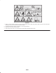
Safety and Instruction Decals Safety decals and instructions are easily visible to the operator and are located near any area of potential danger. Replace any decal that is damaged or lost. 105–0708 1. Danger–Blown object hazard–Keep bystanders away from chute outlet. 98-3110 1. Danger–See Operator’s Manual 2. Danger–Wear ear protection 3. Thrown object hazard–Keep bystanders away. 4. Always wear eye protection 5.
93-6674 1. Crushing hazard, hand—read the instructions before servicing or performing maintenance. 105-4586 1. Entanglement hazard, belt—stay away from moving parts. Do not operate the machine with the shields or guards removed; keep the shields and guards in place. 93-7276 1. Explosion hazard—wear eye protection. 2. Caustic liquid/chemical burn hazard—to perform first aid, flush with water. 3. Fire hazard—no fire, open flames, or smoking. 4. Poison hazard—keep children a safe distance from the battery.
106-0257 1. Warning—read the Operator’s Manual and receive training. Maximum load is 100 lb (45 kg) tongue weight. Do not drive the vehicle with a trailer down hill. Do not lose control of the vehicle and trailer. 2. Crushing/dismemberment hazard of bystanders—do not carry passengers. 3. Warning—do not exceed 15 mph (24 kmh). 4. Stored energy hazard, trailer—do not disconnect the trailer without first putting down the jack.
Specifications General Specifications General Description Frame Suspension Wheels and Tires An upper mid sized debris blower with self–contained power. It is compactly packaged and easily towed by most utility vehicles. The fan can be lowered for highly effective air delivery at turf level or raised for transport. One piece welded steel frame with greasable pivot points 1500 lb. Torflex axle. 5–bolt, 4.5 inch bolt circle hubs Stamped and welded steel wheels. Titan Turf Trac tires 20 x 10.00–8, 4 ply.
Setup Note: Use this chart as a checklist to ensure that all parts have been received. Without these parts, total setup cannot be completed. Description Qty. Use Hitch Assembly 1 Mount to debris blower Operator’s Manual 1 Read before operating the machine. Parts Catalog 1 Registration card 1 Note: Determine the left and right sides of the machine from the normal operating position. Fill out and return to Toro. 2.
5. Slowly pour electrolyte into each cell until the electrolyte level is up to the lower part of the tube (Fig. 3). Warning Charging the battery produces gasses that can explode. 1 Never smoke near the battery and keep sparks and flames away from battery. 2 8. When the battery is fully charged, disconnect the charger from the electrical outlet and from the negative and positive battery posts (Fig. 4). 3 9.
2 1 2 Figure 7 1 1. Hitch clevis 2. Hitch tube • Raise or lower hitch clevis to position approximately level with tow vehicle hitch. • Secure with bolts and locknuts previously removed. 7. Remove clevis pin and hair pin cotter securing hitch tube to frame tube (Fig. 8). Figure 5 1. Jack 2. Pin 2 3. Adjust jack height until blower frame is parallel with the ground. 1 4. Insert hitch tube into frame tube (Fig. 6). Secure tube to frame with a clevis pin and hair pin cotter. 3 4 Figure 8 2 1 1.
Removing Debris Blower From Tow Vehicle Greasing The Blower Before the debris blower is operated, it must be greased to ensure proper lubricating characteristics; Refer to greasing the blower in the maintenance section; Page 15. Failure to properly grease the unit will result in premature failure of critical parts. 1. Park debris blower on a level surface and block wheels. Caution Before leaving the operator’s seat on the tow vehicle, wait for the engine and all moving parts to stop. 2.
Fill Fuel Tank Before Operating Fuel tank capacity is approximately 7 gallons. Caution Danger If you leave the key in the ignition switch, someone could accidently start the engine and seriously injure you or other bystanders. Because gasoline is flammable, caution must be used when storing or handling it. Do not fill fuel tank while engine is running, hot or when machine is in an enclosed area. Vapors may build up and be ignited by a spark or flame source many feet away.
Operation Note: Determine the left and right sides of the machine from the normal operating position. Controls Key Switch The key switch (Fig. 12), used to start and stop the engine, has three positions: off, run, and start. 1 To start the engine, rotate the key to the start position. Release the key when engine starts and it will move automatically to the run position. 2 To stop the engine, rotate the key to the off position. Figure 13 1. Chute Direction switch 2.
Starting Instructions Adjusting Discharge Direction Starting the Engine The direction of the discharge opening can be changed from right to left by moving the switch on the remote control. 1. Remove remote control from storage position on back of battery cover (Fig. 15). Operating Tips 2. Unwind control harness (Fig. 15) from storage hooks and place remote control on tow vehicle. Warning Discharged air has considerable force and could cause injury or loss of footing.
Maintenance Note: Determine the left and right sides of the machine from the normal operating position. Greasing the Blower The debris blower must be lubricated after every 8 hours of operation with a no. 2 lithium-based grease. The fittings and locations are as follows: • Front fan mount pivots (2) (Fig. 16) • Rear fan mount pivots (2) (Fig. 17) • Fan bearing (2) (Fig. 18) Figure 18 Servicing the Air Cleaner Foam Element: Clean and oil after every 25 operating hours, or yearly, whichever occurs first.
2 2 1 1 4 3 m–3247 Figure 20 5 7 1. Foam element 2. Oil 6 Checking the Paper Element 8 Inspect the element for tears, an oily film, damage to the rubber seal, excessive dirt, or other damage (Fig. 21). If any of these conditions exit, replace the filter. m–3214 Figure 19 1. 2. 3. 4. Air cleaner cover Knob Cover nut Cover 5. 6. 7. 8.
Servicing the Engine Oil Change oil after the first 50 operating hours and then every 100 operating hours thereafter. Note: Change oil more frequently when operating conditions are extremely dusty or sandy. Oil Type: Detergent oil (API service SG, SH, SJ, or higher) Crankcase Capacity: w/filter, 2.1 qt. (2 l) Viscosity: See table below USE THESE SAE VISCOSITY OILS 1 10W–30, 10W–40 Figure 22 1. Oil drain hose plug 5W–20, 5W–30 –20 °F 0 –30 °C –20 20 32 40 –10 0 80 60 10 20 5.
2. Remove capscrew and nut securing tensioner guide to blower frame (Fig. 25). Belt tension will be released when capscrew is removed. 3 1 2 1 2 m–1256 Figure 23 1. Oil filter 2. Gasket 3. Adapter 6. Install the replacement oil filter to the filter adapter. Turn the oil filter clockwise until the rubber gasket contacts the filter adapter, then tighten the filter an additional 1/2 turn (Fig. 23). Figure 25 1. Tensioner guide 7.
1 2 3 1262 Figure 28 1. Filler caps 2. Lower part of tube 3. Plates Adding Water to the Battery The best time to add distilled water to the battery is just before you operate the traction unit. This lets the water mix thoroughly with the electrolyte solution. Figure 27 5. Insert capscrew into aligned guide holes and secure with nut. If holes are not exactly aligned, rotate guide to the next higher hole until aligned. 1. Clean the top of the battery with a paper towel. 6.
Servicing the Spark Plugs 2 Check the spark plugs after every 200 operating hours. Ensure that the air gap between the center and side electrodes is correct before installing each spark plug. Use a spark plug wrench for removing and installing the spark plugs and a gapping tool/feeler gauge to check and adjust the air gap. Install new spark plugs if necessary. 3 1 0.030 in. (0.76 mm) Type: Champion Premium Gold 2071 or Champion RC12YC (or equivalent) Air Gap: 0.030 in. (0.
Draining the Fuel Tank 5. Place a drain pan under the fuel lines to catch any leaks, then remove the filter from the fuel lines. 6. Install a new filter and move the hose clamps close to the filter. Danger 7. Remove the clamp blocking fuel flow and open the fuel valves. In certain conditions, gasoline is extremely flammable and highly explosive. A fire or explosion from gasoline can burn you and others and can damage property. • Drain gasoline from the fuel tank when the engine is cold.
Troubleshooting PROBLEM Starter does not crank Engine g will not start, starts hard, or f il to fails t keep k running. i Engine g loses power Engine g overheats. There is excessive vibration. There is lack of adequate air flow. POSSIBLE CAUSES CORRECTIVE ACTION 1. Battery is dead. 1. Charge the battery. 2. Electrical connections are corroded or loose. 2. Check electrical connections for good contact. 3. Relay or switch is defective. 3. Contact Authorized Service Dealer. 1.
Cleaning and Storage 1. Stop the engine and remove the key. 2. Remove dirt and grime from the external parts of the entire machine, especially the engine. Clean dirt and chaff from the outside of the engine’s cylinder head fins and blower housing. 3. Service the air cleaner; refer to Servicing the Air Cleaner. 4. Grease the blower; refer to Greasing the Blower. 5. Change the crankcase oil; refer to Servicing the Engine Oil. 6.
The Toro General Commercial Products Warranty A Two-Year Limited Warranty Conditions and Products Covered The Toro Company and its affiliate, Toro Warranty Company, pursuant to an agreement between them, jointly warrant your 1996 or newer Toro Commercial Product (“Product”) purchased after January 1, 1997, to be free from defects in materials or workmanship for two years or 1500 operational hours*, whichever occurs first.