
Operator's Manual


WARNING
Batteryterminalsormetaltoolscouldshort
againstmetalcomponentscausingsparks.
Sparkscancausethebatterygassestoexplode,
resultinginpersonalinjury.
•Whenremovingorinstallingthebattery,do
notallowthebatteryterminalstotouchany
metalpartsofthemachine.
•Donotallowmetaltoolstoshortbetweentry
terminalsandmetalpartsofthemachine.
2.Attachthepositivecable(redcable)tothepositive
(+)terminal.
WARNING
Incorrectbatterycableroutingcoulddamage
theblowerandcablescausingsparks.Sparks
cancausethebatterygassestoexplode,
resultinginpersonalinjury.
•Alwaysdisconnectthenegative(black)
batterycablebeforedisconnectingthe
positive(red)cable.
•Alwaysconnectthepositive(red)battery
cablebeforeconnectingthenegative(black)
cable.
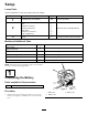
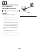
G020712
1
2
3
4
5
Figure4
1.Batterybox4.Batteryclips
2.Negativebatterypost5.Positivebatterypost
3.Batterycover
3.Attachthenegativecable(blackcable)tothenegative
(-)terminalofthebattery.
4.Coattheterminalsandmountingfastenerswith
petroleumjellytopreventcorrosion.
5.Installthebatterycoverandsecurewiththeclips.
2
MountingtheHitchtothe
DebrisBlower
Partsneededforthisprocedure:
1Debrisblowerassembly
1Hitch
2
Bolt(3/8x3inches)
2
Flangenut(3/8inch)
1Hitchclevis
2
Bolt(5/8x4–1/2inch)
2
Locknut(5/8inch)
Procedure
1.Positionthedebrisbloweronaat,levelsurface.
2.Insertthehitchtubeintotheframebrackets
(
Figure5).Securethetubetotheframewith2bolts
(3/8x3inches)andangenuts(3/8inch).
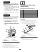
Figure5
1.Framebrackets3.Hitchclevis
2.Hitchtube
Note:Thehitchtubecanberotated180degreesto
accommodatedifferenthitchheights.
9